Visual test device for damaged form of pile-soil contact surface of specially-shaped pile and use method

A test device and a technology for special-shaped piles, which are applied in the field of model tests, can solve the problems that there is no application or research on the contact surface between structures and soil, and the contact form cannot be completely truthfully reflected, and achieves simple structure, convenient operation and low cost. Effect

Active Publication Date: 2016-06-29
HOHAI UNIV
View PDF12 Cites 21 Cited by
  • Summary
  • Abstract
  • Description
  • Claims
  • Application Information

AI Technical Summary

Problems solved by technology

At present, most of the research on shear failure and shear band of contact surface at home and abroad is aimed at the situation of plane shear. However, in the actual field of geotechnical engineering, such as between pile foundation and soil, the contact problem is a three-dimensional ring Contact problem, plane

Method used


Image

  • Visual test device for damaged form of pile-soil contact surface of specially-shaped pile and use method
  • Visual test device for damaged form of pile-soil contact surface of specially-shaped pile and use method
  • Visual test device for damaged form of pile-soil contact surface of specially-shaped pile and use method

Examples


Embodiment 1

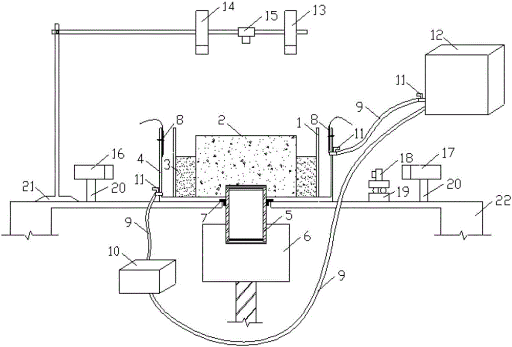
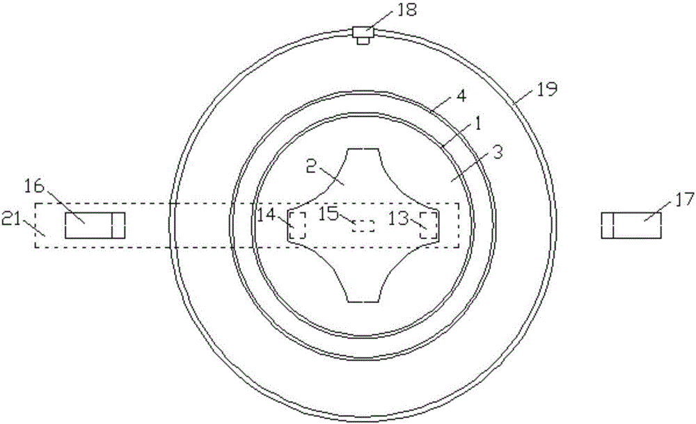
[0037] The visual test device for the failure mode of the pile-soil contact surface of special-shaped piles, the structure is as follows Figure 1-2 As shown, it includes a platform 22, a model pile 2, a model tank 1, a water bath 4, a temperature control system, a laser source and a digital camera.

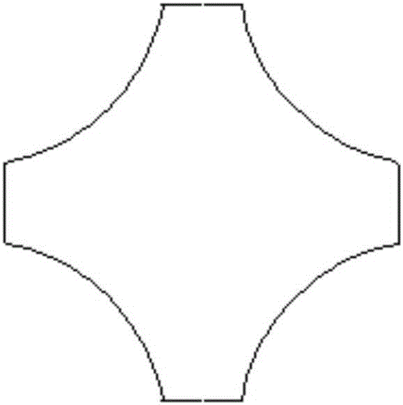
[0038] Model pile 2 is a model pile that simulates the actual full scale of the special-shaped pile on site. The pile body can be made of concrete or PC (polycarbonate) or plexiglass materials, such as Figure 3-5 As shown, the cross-sectional shape of the model pile 2 can be X-shaped, Y-shaped, H-shaped or circular, and the equivalent diameter is 400 ~ 600mm (the model pile of this embodiment is an X-shaped equivalent diameter of 400mm, made of concrete production). The surface of the model pile 2 can be smooth or rough.

[0039] The model pile 2 is set in the model tank 1, surrounded by transparent soil 3, the model tank 1 is set in the water bath 4, both the model tank 1 and...


PUM

PropertyMeasurementUnit
Diameteraaaaaaaaaa
Heightaaaaaaaaaa
Side lengthaaaaaaaaaa

Abstract

The invention provides a visual test device for a damaged form of a pile-soil contact surface of a specially-shaped pile and a use method. The test device comprises a bearing platform, a model pile, a model tank, a water bath tank, a temperature control system, a laser source and a digital camera device, wherein the model pile is arranged as a full-scale specially-shaped pile and is arranged in the model tank; transparent soil is arranged on the periphery of the model pile; the model tank is arranged in the water bath tank; a rotating shaft hole is formed on the bottom of the model tank while a rotating shaft is arranged in the model tank; the rotating shaft is used for driving the model pile to generate vertical displacement or torsional displacement; the temperature control system is matched with the water bath tank and is used for adjusting the temperature of the pile-soil contact surface; and the laser source and the digital camera device are arranged on the upper side and side wall of the model tank. According to the visual test device provided by the invention, the visual observation for shear deformation of concave surface of the cross section of the specially-shaped pile can be realized; the shearing damage characteristics of different loading modes, different temperatures and different piles can be compared; the visual test device has significance in research on shearing of the contact surface of the full-scale model pile; the visual test device provided by the invention has the advantages of simple structure, convenience in operation, easiness in realization and lower cost.

Description

Technical field [0001] The present invention involves a variety of vibrato pile-soil contact surface destruction form visual testing devices and use methods, which belongs to the field of model test technology. Background technique [0002] The interaction between building components and soil has always been an important topic of geotechnical research.When using the numerical simulation method to analyze the interaction of the building component and the soil, the setting of contact problems has a huge impact on the accuracy and reliability of the calculation results.At present, most of the research of contact surface cutting and cutting belt at home and abroad is mostly aimed at plane cutting. However, in the actual field of geotechnical engineering, such as the pile foundation and the soil bodyIn contact, plane contact cannot completely truthfully reflect the form of contact.The displacement of the ring contact surface is not easy to measure, resulting in relatively small circul...

Claims


Application Information

Patent Timeline
IPC IPC(8): G01N3/24
CPCG01N3/24
Inventor 李春红孔纲强孟珍珠刘璐孙学谨张鑫蕊
Owner HOHAI UNIV
Why Eureka
Try Eureka