Micro camera lens

a micro-camera and lens technology, applied in the field of optical imaging system of lenses, can solve the problems of poor imaging quality of most known products with better tolerance limits, difficulty in maintaining stable quality in mass production, and insufficient design of specific structural parameters to achieve better optical effects, etc., to achieve enhanced resolution power of the entire lens, improved image quality, and reduced tolerance sensitivity

Inactive Publication Date: 2012-03-01
ZHEJIANG SUNNY OPTICAL CO LTD
View PDF5 Cites 16 Cited by
  • Summary
  • Abstract
  • Description
  • Claims
  • Application Information

AI Technical Summary

Benefits of technology

[0023]Since the micro camera lens provided in the present invention employs a combination of aspheric lens, the resolving power of the entire lens is enhanced, and the lens has excellent imaging quality; in addition, through t...

Problems solved by technology

However, how to design the specific structural parameters to attain better optical effect has always been a major challenge in the optical lens manufacturing industry.
But it is easy for such a design to result in low tolerance limit and increased lens processing requirements, bring difficulties in maintaining stable quality in mass production.
In contrast, most known products with better tolerance limit have poor imaging quality.
Tolerance limit is quit...

Method used


Image

  • Micro camera lens
  • Micro camera lens
  • Micro camera lens

Examples


embodiment 1

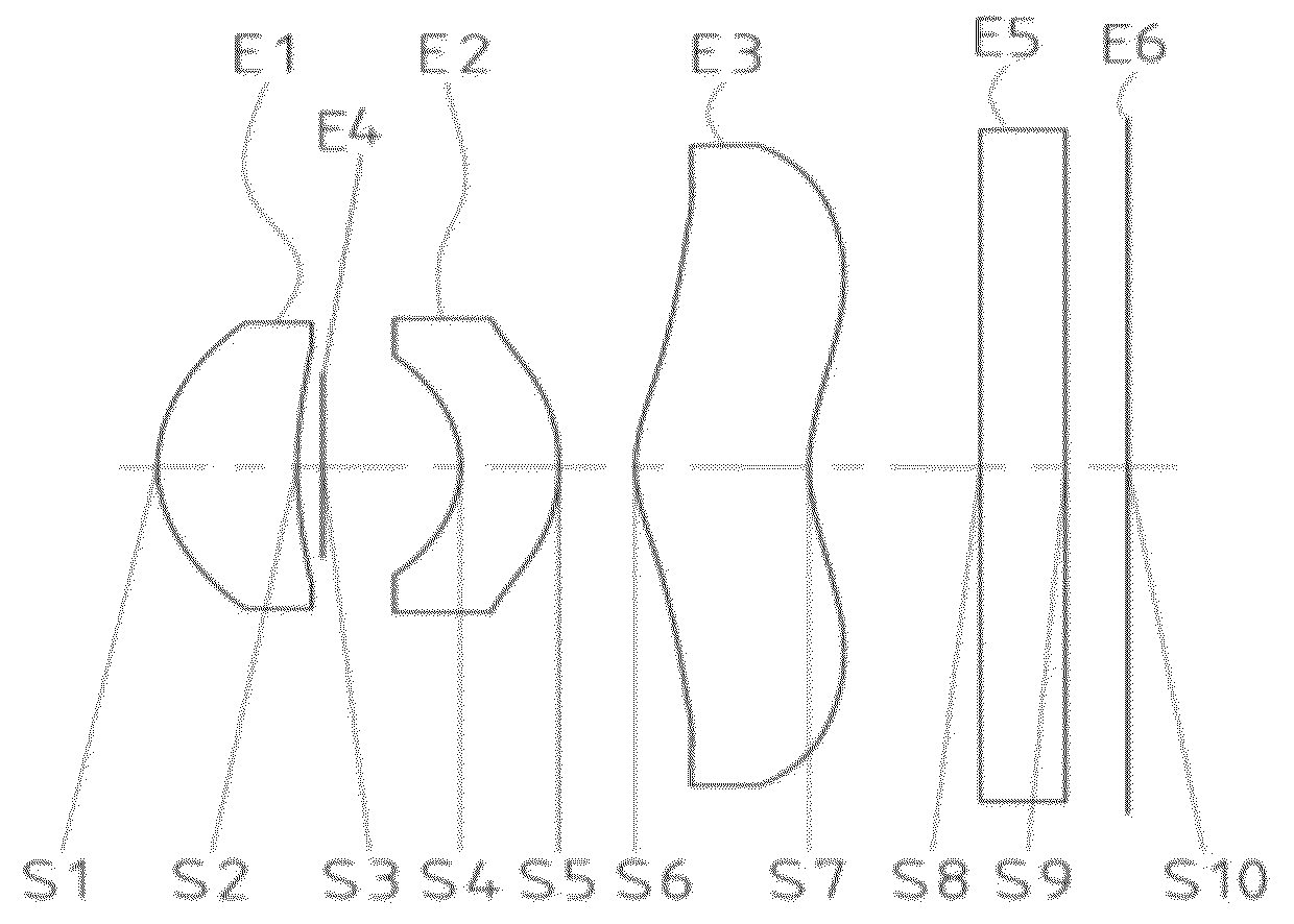
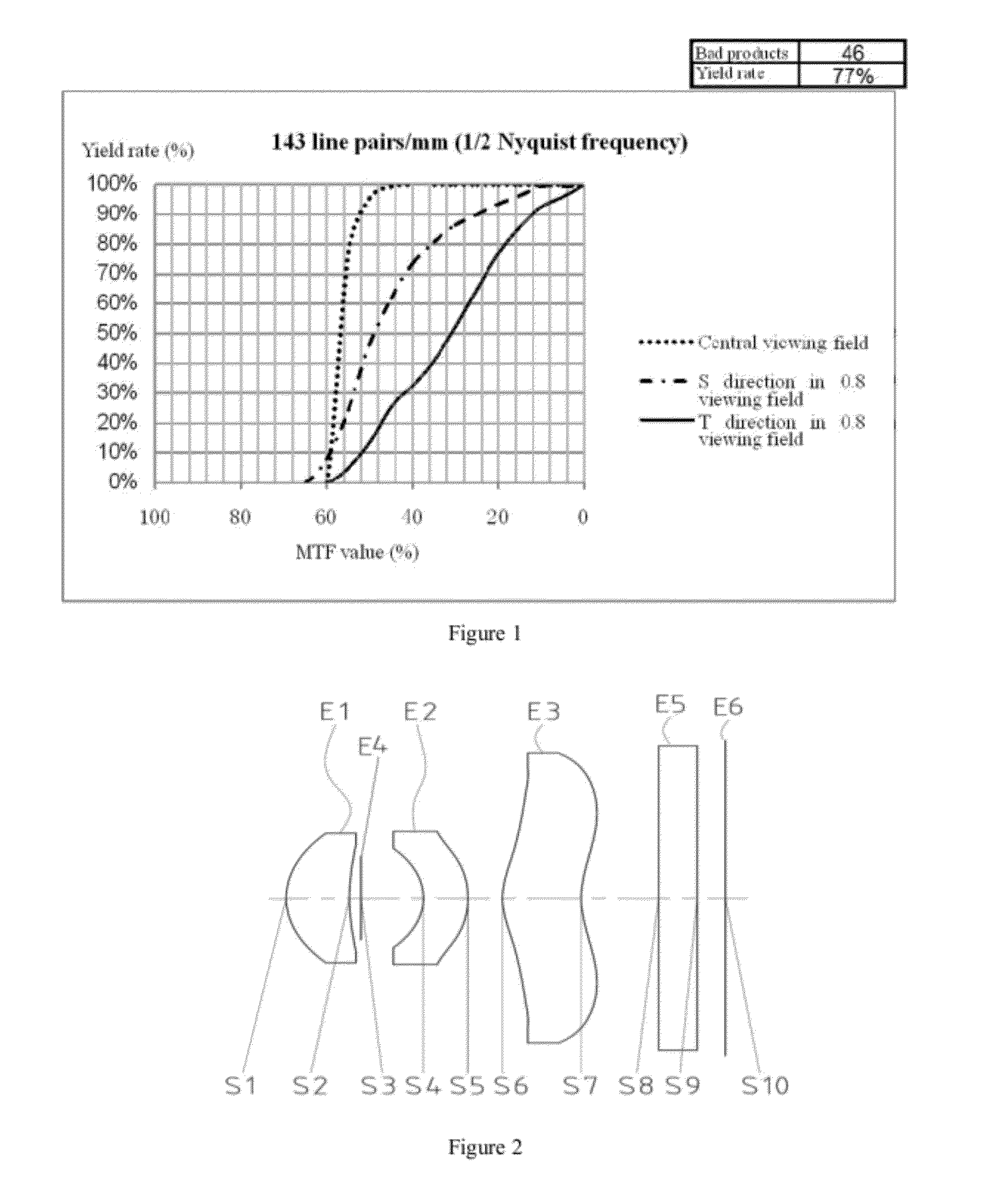
[0053]FIG. 2 shows the structure of the micro camera lens in Embodiment 1 of the present invention. As shown in FIG. 2, the micro camera lens comprises three aspheric lenses. In addition, when counted from the object side to the image side along the optical axis, the elements include: a first lens E1 with positive diopter, a diaphragm E4, a second lens E2 with negative diopter, a third lens E3 with positive diopter, a filter E5, and an imaging plane E6.

[0054]In this embodiment, the first lens is a meniscus convex-concave lens, with the convex side facing the object side and the concave side facing the image side; the second lens is a meniscus concave-convex lens, with the concave side facing the object side and the convex side facing the image side; the third lens is a bow-shaped convex-concave lens, with the convex side facing the object side, the concave side facing the image side, and the central convex part facing the object side.

[0055]The Abbe number VP1 of the first lens E1 is...

embodiment 2

[0066]FIG. 8 shows the structure of the micro camera lens in Embodiment 2 of the present invention. As shown in FIG. 8, the micro camera lens in this embodiment comprises three aspheric lenses.

[0067]In addition, when counted from the object side to the image side along the optical axis, the elements include: a first lens E1′ with positive diopter, a diaphragm E4′, a second lens E2′ with negative diopter, a third lens E3′ with positive diopter, a filter E5′, and an imaging plane E6′.

[0068]In this embodiment, the three aspheric lenses are in the same shapes as the lenses in Embodiment 1, i.e., the first lens is a meniscus convex-concave lens, the second lens is a meniscus concave-convex lens, and the third lens is a bow-shaped convex-concave lens.

[0069]The Abbe number VP1 of the first lens E1′ is VP1=56.1, and the Abbe number VP2 of the second lens E2′ is VP2=23.0.

[0070]The focal length f1 of the first lens is 3.15, the focal length f2 of the second lens is −5.06, and the focal length...


PUM


Abstract

The present invention discloses a micro camera lens, comprising three aspheric lenses and a diaphragm, wherein, the three lenses have positive diopter, negative diopter, and positive diopter, respectively, and meet the following expression: VP1>50 and VP2<35; Where, VP1 and VP2 are Abbe numbers of the first lens and second lens, respectively. Since the micro camera lens provided in the present invention employs a combination of aspheric lens, the resolving power of the entire lens is enhanced, and the lens has excellent imaging quality; in addition, in an appropriate optical parameter design, the lens has lower tolerance sensitivity and improved tolerance limit, and can be produced reliably by mass production. Thus, the micro camera lens provided in the present invention attains favorable technical efficacies.

Description

FIELD OF THE INVENTION[0001]The present invention relates to an optical imaging system of lens, in particular to a high-quality and tolerance-insensitive micro lens composed of three aspheric lenses.BACKGROUND OF THE INVENTION[0002]Micro camera lenses have been researched and developed widely in the prior art; especially, camera lenses composed of three lenses have been developed rapidly. However, how to design the specific structural parameters to attain better optical effect has always been a major challenge in the optical lens manufacturing industry.[0003]Usually, high-quality camera lenses are implemented with one or more aspheric lenses, because aspheric lenses have preferable radius of curvature and can maintain good aberration correction performance, and thereby improves the overall resolution and quality of the camera lens. But it is easy for such a design to result in low tolerance limit and increased lens processing requirements, bring difficulties in maintaining stable qu...

Claims


Application Information

Patent Timeline
IPC IPC(8): G02B13/18
CPCG02B13/0035
Inventor DAI, FUJIANHUANG, LINLI, HUAN
Owner ZHEJIANG SUNNY OPTICAL CO LTD
Why Eureka
Try Eureka