
Method and apparatus for frequency domain reverse-time migration with source estimation

Inactive Publication Date: 2012-03-01
SEOUL NAT UNIV R&DB FOUND
View PDF4 Cites 17 Cited by
  • Summary
  • Abstract
  • Description
  • Claims
  • Application Information

AI Technical Summary

Benefits of technology

[0018]Next, the fidelity of the reverse-time migration for IFP original Marmousi data disclosed in the paper “Marmousi, model and data, in Versteeg, R., and Grau, G., Eds., The Marmousi experience, Proceedings of the 1990 EAEG workshop on Practical Aspects of Seismic Data Inversion: EAEG, 5-16” (Bourgeois, A., Bourget, M., Lailly, P., Poulet, M., Ricarte, P., and Versteeg, R., 1991) has been investigated. In this model, frequencies ranging from 0.34578 to 60 Hz were used in intervals of 0.34578 Hz, the total recording time was 3 seconds, and the sampling interval was 0.004 seconds. The grid interval was 16 m, and the number of shots was 240. FIG. 5 is a graph plotting the relative signal amplitudes of the estimated source wavelet for an IFP original Marmousi data and the true source wavelet. It is seen from FIG. 5 that the estimated source wavelet nearly approximates the true source wavelet. FIG. 5 describes that the boundaries of the layers are more clearly located, which demonstrates that source wavelet estimation enhances the resolution of migration images.

Problems solved by technology

Various sources were used in seismic exploration, but it was not easy to accurately detect the waveforms of the sources since there are non-linear wave propagation and noise near the sources, coupling between the sources and receives, etc.
Accordingly, the existing reverse-time migration failed to reflect accurate sources, which became a factor limiting the resolution of reverse-time migration.

Method used


Image

  • Method and apparatus for frequency domain reverse-time migration with source estimation
  • Method and apparatus for frequency domain reverse-time migration with source estimation
  • Method and apparatus for frequency domain reverse-time migration with source estimation

Examples


Embodiment Construction

[0024]The following description is provided to assist the reader in gaining a comprehensive understanding of the methods, apparatuses, and / or systems described herein. Accordingly, various changes, modifications, and equivalents of the methods, apparatuses, and / or systems described herein will be suggested to those of ordinary skill in the art. Also, descriptions of well-known functions and constructions may be omitted for increased clarity and conciseness.

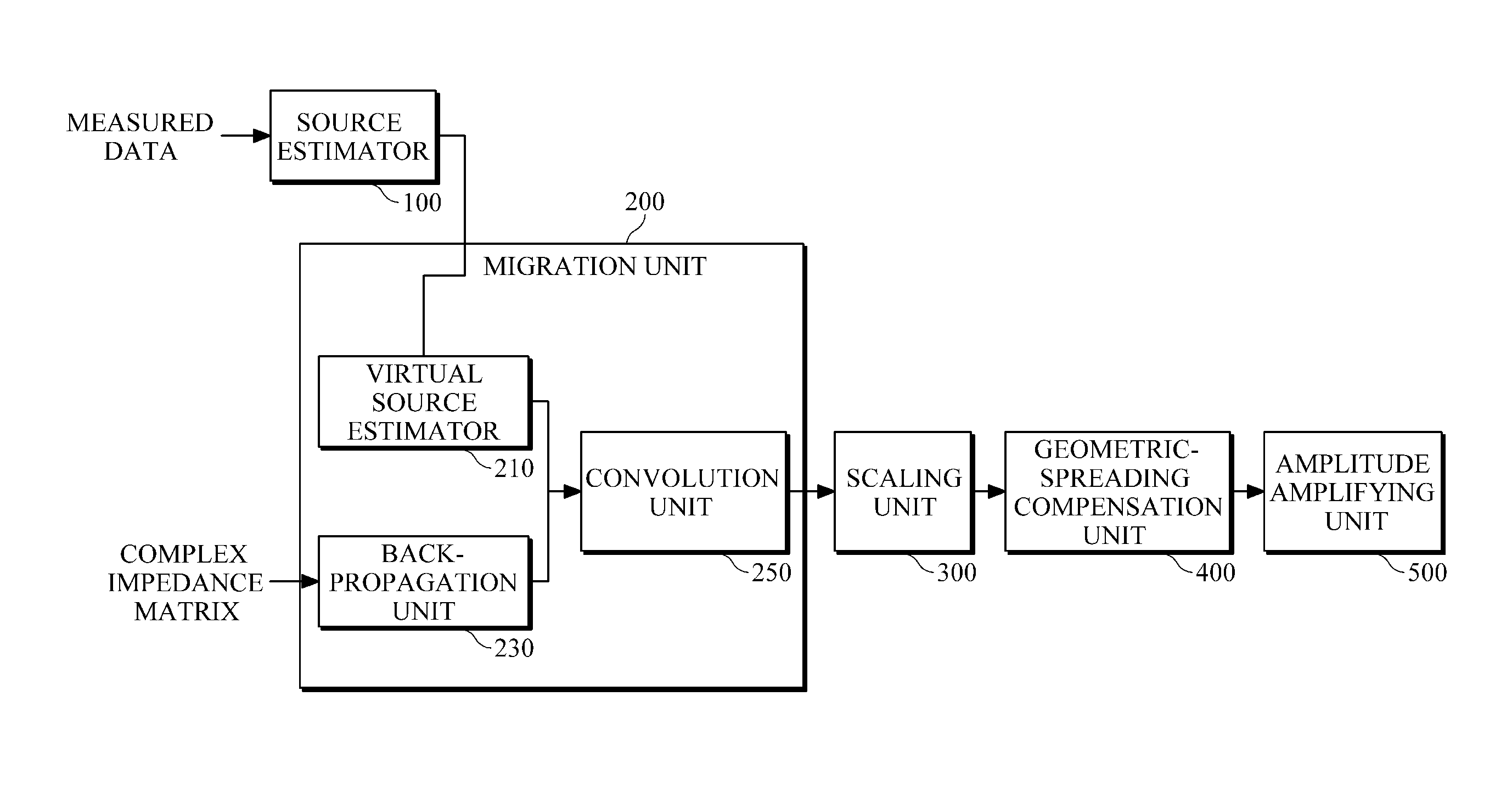
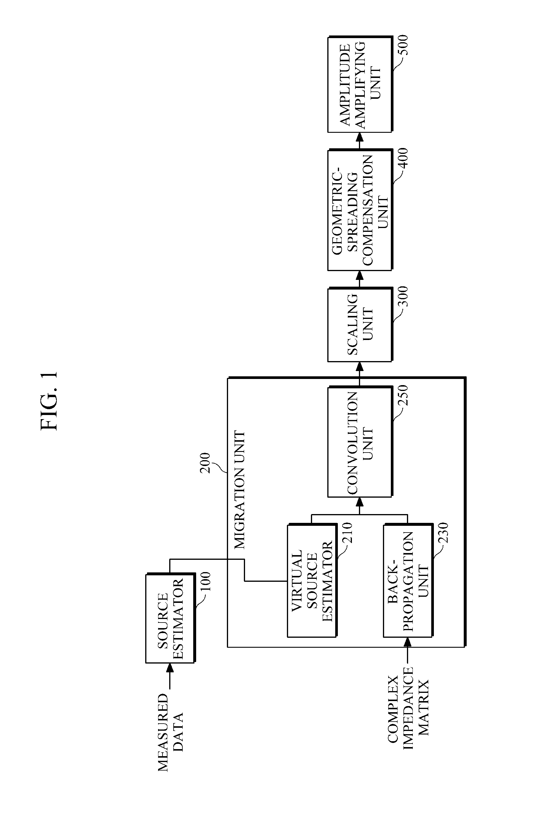
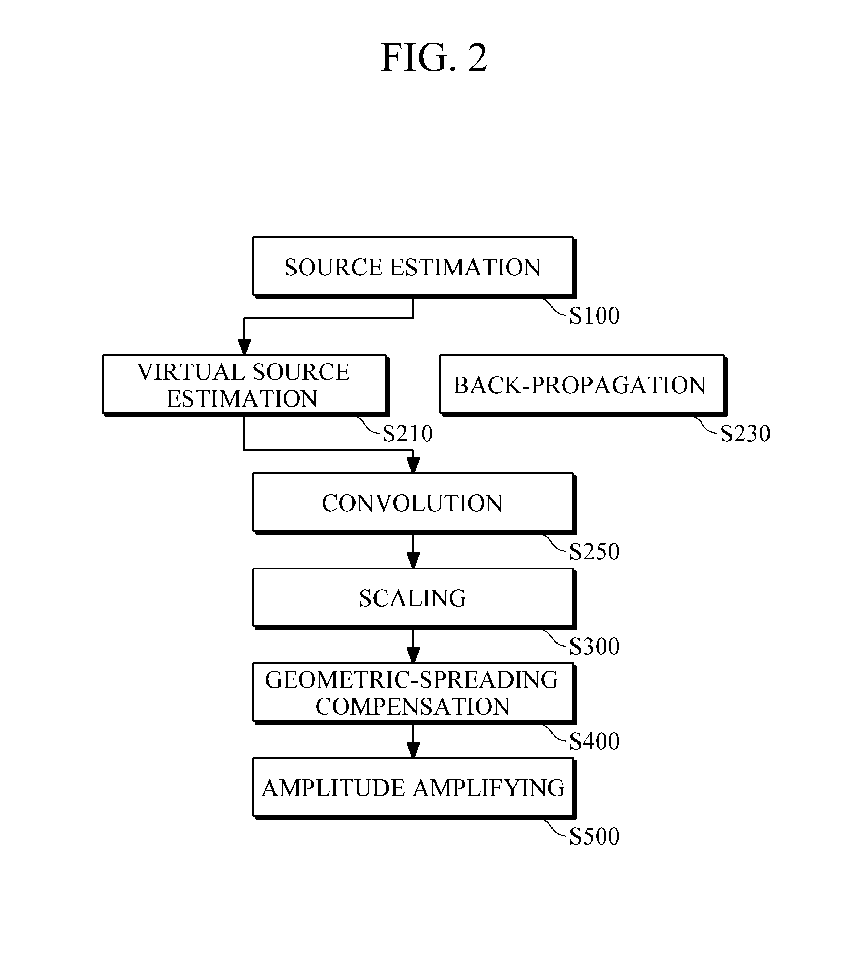
[0025]FIG. 1 is a diagram illustrating an example of a reverse-time migration apparatus. As illustrated in FIG. 1, the reverse-time migration apparatus includes a source estimator 100 that estimates sources from measured data on receivers, and a migration unit 200 that receives information about the estimated sources to perform reverse-time migration in the frequency domain.

[0026]According to an example, the migration unit 200 includes a back-propagation unit 230 that back-propagates the measured data on the receivers, a virtual s...


PUM


Abstract

Provided is seismic imaging, particularly, reverse-time migration for generating a real subsurface image from modeling parameters calculated by waveform inversion, etc. A frequency-domain reverse-time migration apparatus includes: a source estimator configured to estimate sources from data measured on a plurality of receivers; and a migration unit configured to receive information about the sources estimated by the source estimator and to perform reverse-time migration in the frequency domain. The source estimator estimates the sources by updating an initial source vector using incremental changes according to a full Newton method. In more detail, the migration unit includes: a back-propagation unit configured to back-propagate the measured data; a virtual source estimator configured to estimate virtual sources from the sources estimated by the source estimator; and a convolution unit configured to convolve the back-propagated measured data with the virtual sources and to output the results of the convolution.

Description

CROSS-REFERENCE TO RELATED APPLICATION[0001]This application claims the benefit under 35 U.S.C. §119(a) of a Korean Patent Application No. 10-2010-0082161, filed on Aug. 24, 2010, the entire disclosure of which is incorporated herein by reference for all purposes.BACKGROUND[0002]1. Field[0003]The following description relates to seismic imaging, and more particularly, to reverse-time migration for generating a real subsurface image from modeling parameters calculated by waveform inversion, etc.[0004]2. Description of the Related Art[0005]A two-way migration method requires significantly more computational resources than a one-way migration method. However, since the two-way migration method has substantially no dip limitation as well as processing multiarrivals, the two-way migration method allows seismic imaging regardless of the inclination of a reflection surface and also can preserve the real amplitudes of seismic wavefields. For these reasons, the two-way migration method has b...

Claims


Application Information

Patent Timeline
IPC IPC(8): G01V1/28
CPCG01V1/305G01V1/364
Inventor SHIN, CHANGSOO
Owner SEOUL NAT UNIV R&DB FOUND
Learn More