Pump Apparatus

Active Publication Date: 2012-03-01
HITACHI ASTEMO LTD
View PDF4 Cites 3 Cited by
  • Summary
  • Abstract
  • Description
  • Claims
  • Application Information

AI Technical Summary

Benefits of technology

[0004]It is an object of the present invention to solve the above-described problem in the pump apparatus of the conventional art and to provide a pump apparatus capable of ensuring high accuracy in positioning of gear shafts and improving assembling efficiency thereof.

Problems solved by technology

However, if the dimensional accuracy of parts is excessively enhanced, an assembling efficiency will be lowered.
Due to occurrence of the clearance, the gear shafts and gears supported on the gear shafts undergo undesirable displacement, and a leakage of working oil through the clearance is caused to thereby reduce a pump efficiency.

Method used


Image

  • Pump Apparatus
  • Pump Apparatus
  • Pump Apparatus

Examples


first embodiment

[0048]A pump apparatus according to the present invention will be explained hereinafter with reference to the accompanying drawings.

[0049][General Construction]

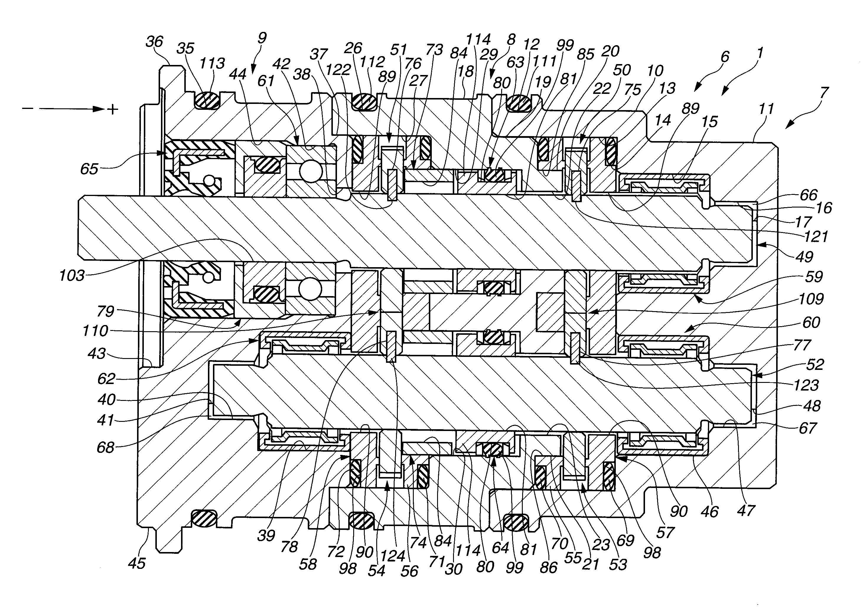
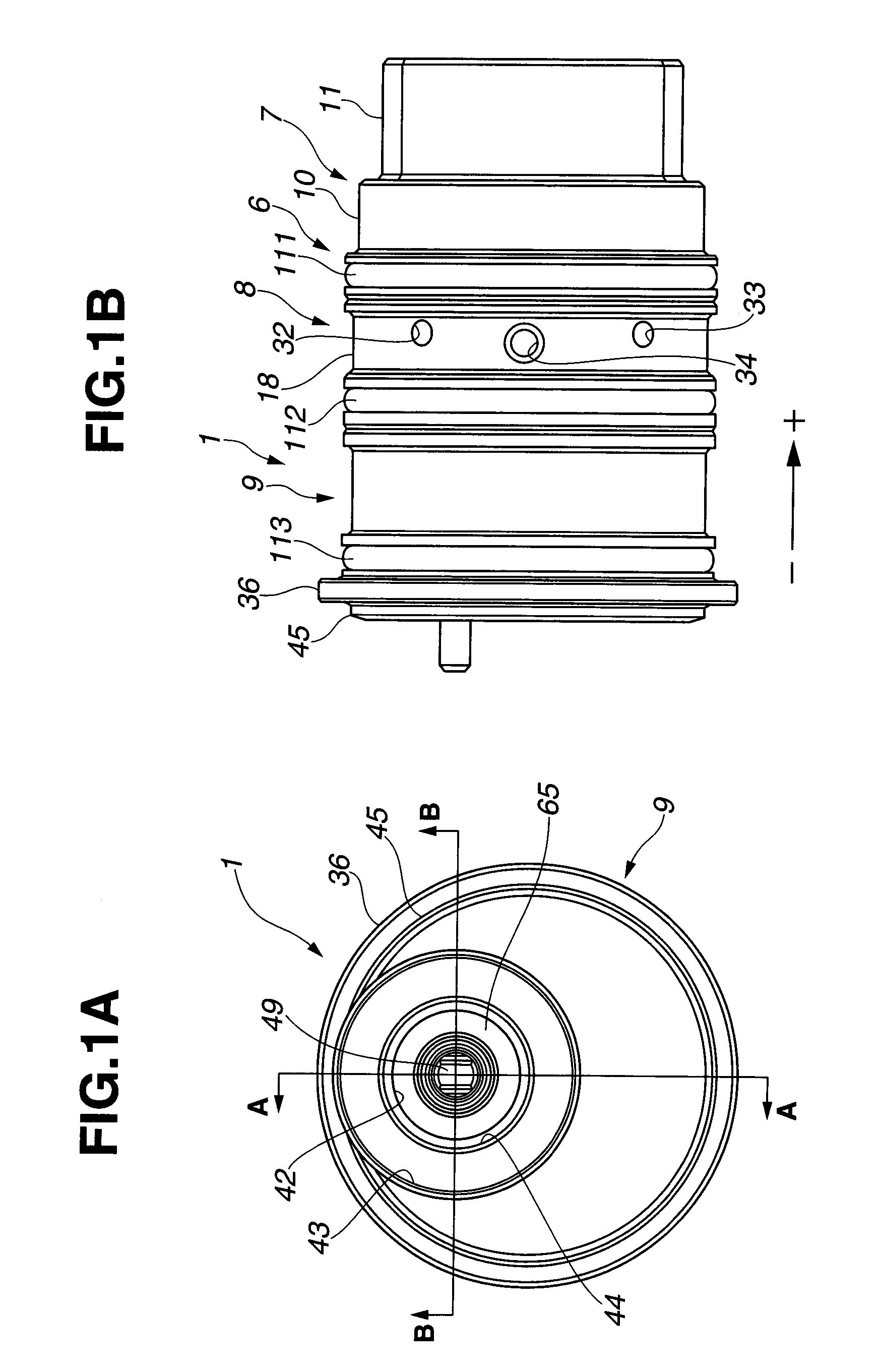
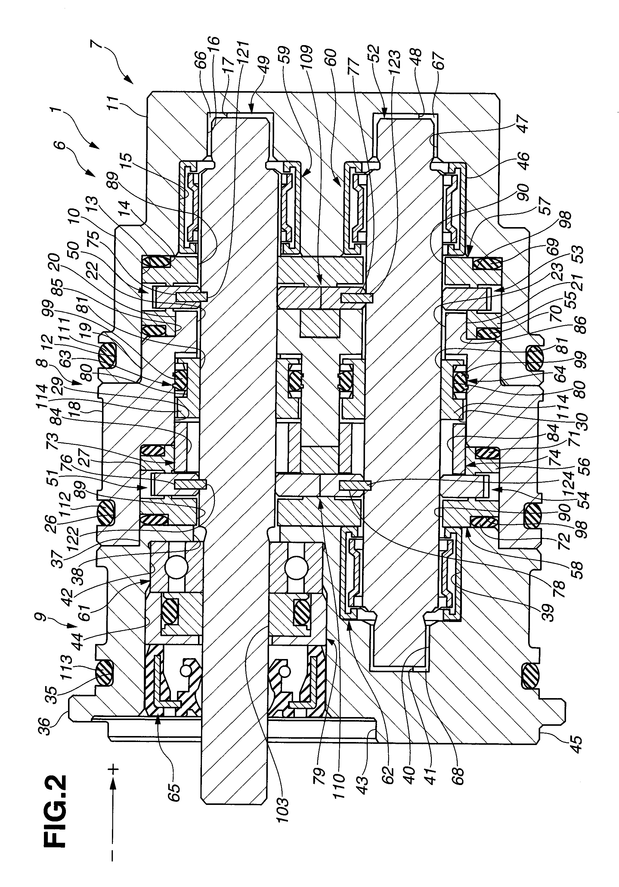
[0050]FIG. 1A is an external view of pump apparatus 1 according to a first embodiment of the present invention when viewed from an axial outside of pump apparatus 1. FIG. 1B is an external view of pump apparatus 1 when viewed from a radial outside of pump apparatus 1. FIG. 2 is a cross section of pump apparatus 1, taken along line A-A of FIG. 1A. FIG. 3 is a cross section of pump apparatus 1, taken along line B-B of FIG. 1A. FIG. 4 is an exploded perspective view of pump apparatus 1. Pump apparatus 1 may be a pump apparatus for a brake apparatus for increasing fluid pressures in a plurality of wheel cylinders of a vehicle. In this embodiment, pump apparatus 1 is a tandem external gear pump in which fluid pressures in a plurality of wheel cylinders are increased by pumping action of first pump chamber 135 and second pump chamb...

second embodiment

[0205]As shown in FIG. 22, pump apparatus 300 is a tandem internal gear pump which includes first casing 150, center plate 151, second casing 152, third casing 153, first pump mechanism 170 disposed between first casing 150 and center plate 151, and second pump mechanism 171 disposed between center plate 151 and second casing 152.

[0206]First casing 150 has seal groove 182 on an outer circumference surface thereof. Seal groove 182 has a generally U-shaped section and extends over an entire circumference of first casing 150. Seal ring 163 is fitted into seal groove 182. Center plate 151 has seal groove 183 having a generally U-shaped section on an outer circumference surface thereof. Seal groove 183 has a generally U-shaped section and extends over an entire circumference of center plate 151. Seal ring 164 is fitted into seal groove 183. Second casing 152 has seal groove 184 on an outer circumference surface thereof. Seal groove 184 has a generally U-shaped section and extends over a...


PUM

PropertyMeasurementUnit
Forceaaaaaaaaaa
Pressureaaaaaaaaaa

Abstract

A pump apparatus including a drive shaft and a driven shaft supported by bearing members, respectively, a center plate, first external gears, second external gears, first and second side plates, first and second seal members, a pressing means for applying a pressing force between the tooth tips of the respective external gears and the seal surface of the respective seal members in a closing region disposed between the respective external gears and the respective seal members, wherein contact between inner circumferential surfaces of the bearing members and an outer circumferential surface of the drive shaft is established on the side of the closing region, while the tooth tips of the respective external gears and the seal surface of the respective seal members in the closing region are kept pressed against each other by the pressing means.

Description

BACKGROUND OF THE INVENTION[0001]The present invention relates to a pump apparatus.[0002]Japanese Patent Application Unexamined Publication No. 63-277878 discloses a pump apparatus including a gear shaft with a drive gear and a gear shaft with a driven gear meshing with the drive gear. These gear shafts are supported in bearing holes which are formed in a pump body and a cover, respectively.SUMMARY OF THE INVENTION[0003]In order to perform positioning of the gear shafts with high accuracy in such a pump apparatus of the above conventional art, dimensional accuracy of parts must be enhanced and positioning of the pump body, the cover and a side plate relative to each other must be carried out using locating pins or the like. However, if the dimensional accuracy of parts is excessively enhanced, an assembling efficiency will be lowered. On the other hand, if the dimensional accuracy of parts is reduced in consideration of the assembling efficiency, there will occur a clearance between...

Claims


Application Information

Patent Timeline
IPC IPC(8): F01C17/02B23P11/00
CPCF04C2/10F04C2/14Y10T29/49826F04C15/0026F04C2230/602
Inventor MISUNOU, MASAKIKOIZUMI, TOSHIHIRONAKAZAWA, CHIHARU
Owner HITACHI ASTEMO LTD
Why Eureka
Try Eureka