
Cable Connector with Inner Circuit Board for Connecting with Cables

Inactive Publication Date: 2013-05-02
LUXSHARE PRECISION IND SHENZHEN
View PDF9 Cites 11 Cited by
  • Summary
  • Abstract
  • Description
  • Claims
  • Application Information

AI Technical Summary

Benefits of technology

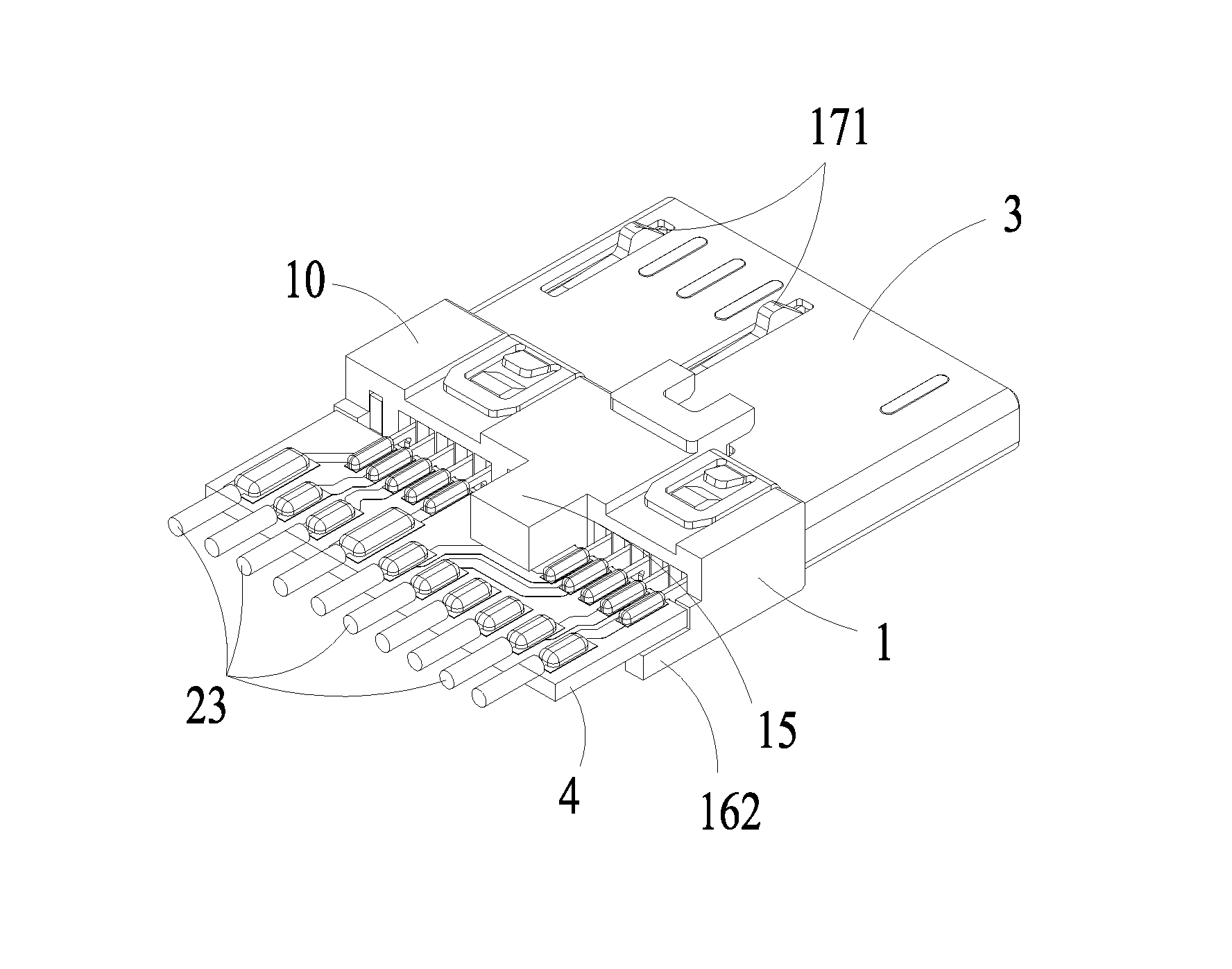
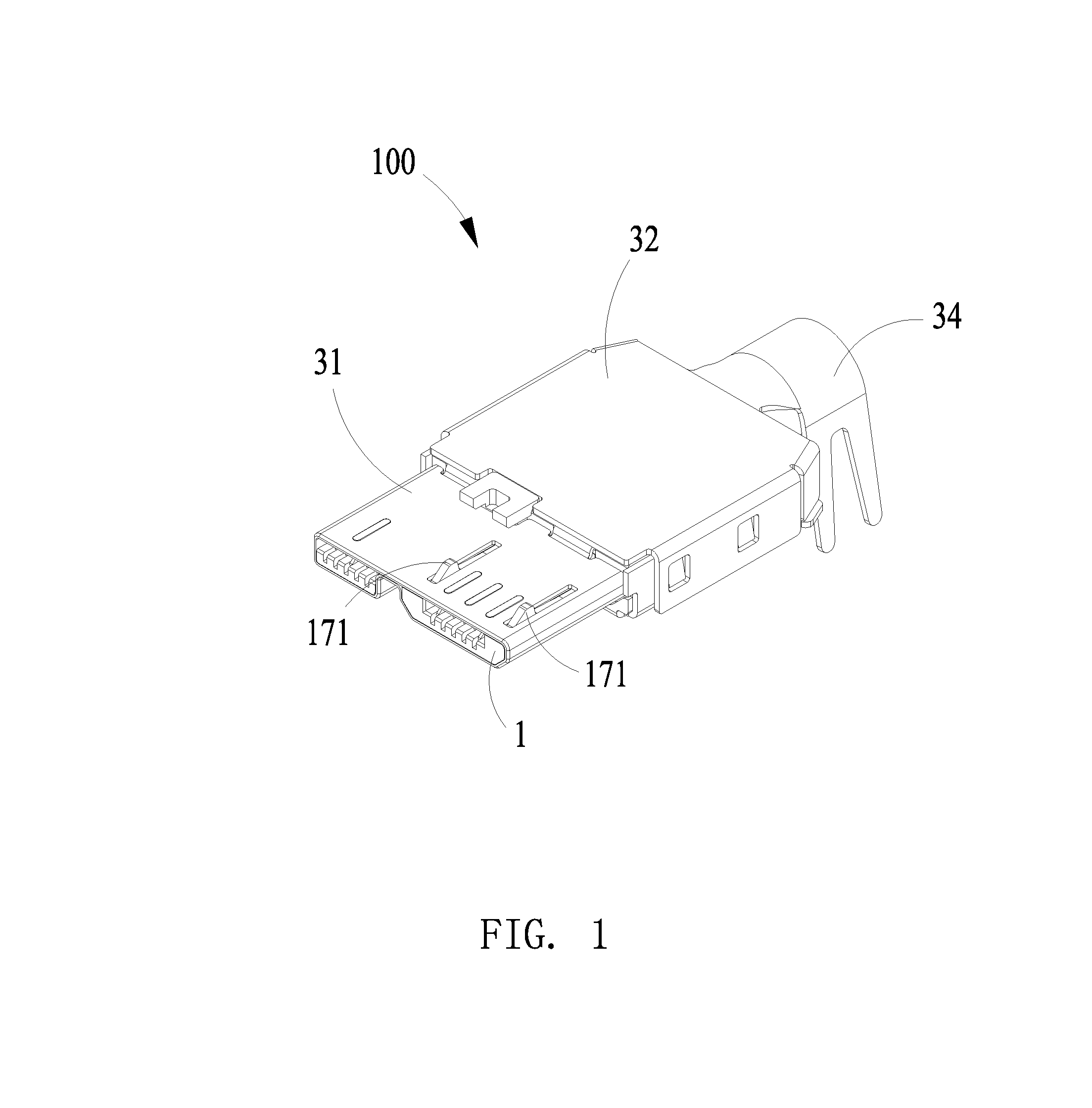
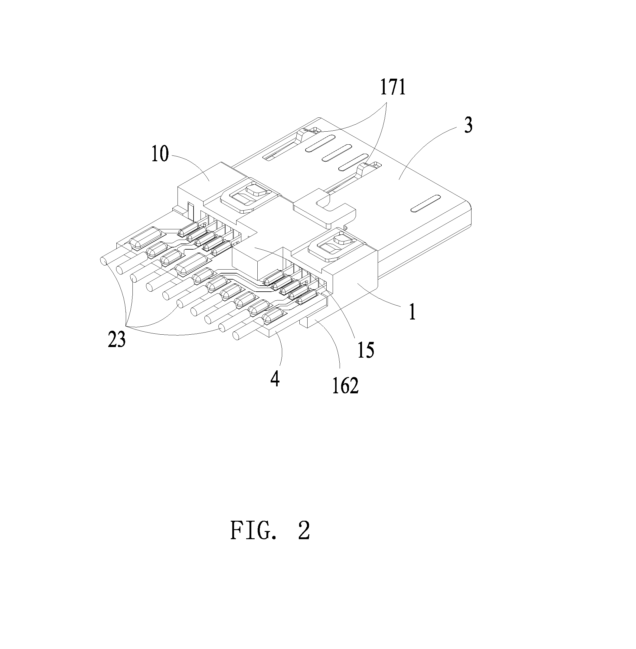
The present invention provides a cable connector that is compatible to the type-A USB 3.0 standard, with improved signal transmission and assembly efficiency. The cable connector includes an insulative housing with a mating portion and two groups of contacts: first and second. The first group includes a power contact, signal contacts, and grounding contacts, while the second group includes high-speed differential signal contacts. The inner circuit board has soldering areas for connecting the contacts to cables. The technical effects of this invention are improved signal transmission and assembly efficiency.

Problems solved by technology

Since the space of the insulative housing is very limited, normally, directly soldering the nine contacts with the cables is difficult.
Under this condition, it is possible that the cables get warped which is harmful to improve product efficiency and reduce cost.

Method used


Image

  • Cable Connector with Inner Circuit Board for Connecting with Cables
  • Cable Connector with Inner Circuit Board for Connecting with Cables
  • Cable Connector with Inner Circuit Board for Connecting with Cables

Examples


first embodiment

[0038]Referring to FIG. 7, a second illustrated embodiment of the present invention discloses another cable connector 100′ which is similar to the cable connector 100 of the The difference therebetween is the pad arrangement of the inner circuit board. In detail, the cable connector 100′ includes an inner circuit board 4′ which includes a first soldering area 41′ and a second soldering area 42′ opposite to the first soldering area 41′. The first soldering area 41′ is provided with ten separated first pads 411′ electrically and mechanically connected to the first soldering sections 213 and the second soldering sections 223 of the contacts 2. The second soldering area 42′ is provided with ten separated second pads 421′ for being connected to the cables 23. In order to meet the requirement of Micro USB 3.0 standard, nine of the first pads 411′ are selected to electrically connect the second pads 421′. Only one of the first pads 411′ does not establish any electrical connection with an...

second embodiment

[0039]Referring to FIG. 8, a third illustrated embodiment of the present invention discloses another cable connector 100″ which is similar to the cable connector 100′ of the The difference therebetween is the pad arrangement of the inner circuit board as well. In detail, the cable connector 100″ includes an inner circuit board 4″ which includes a first soldering area 41″ and a second soldering area 42″ opposite to the first soldering area 41″. The first soldering area 41″ is provided with ten separated first pads 411′ electrically and mechanically connected to the first soldering sections 213 and the second soldering sections 223 of the contacts 2. The second soldering area 42″ is provided with nine separated second pads 421″ for being connected to the cables 23. In order to meet the requirement of Micro USB 3.0 standard, nine of the first pads 411″ are selected to electrically connect the second pads 421″. Only one of the first pads 411″ does not establish any electrical connectio...


PUM


Abstract

A cable connector compatible to USB 3.0 standard includes an insulative housing having, a number of contacts and an inner circuit board for establishing electrically connection between the contacts and cables. The contacts are divided into a first contact group including a number of first contacts and a second contact group including a number of second contacts. The inner circuit board includes a first soldering area having a number of separated first pads connected to the first and the second contacts. The first pads include a first grounding pad connected to a grounding contact of the second contacts. The second soldering area includes a number of separated second pads connected to the cables. At least two adjacent or separated second pads are electrically connected to the first grounding pad for improving high frequency characteristics.

Description

BACKGROUND OF THE INVENTION[0001]1. Field of the Invention[0002]The present invention relates to a cable connector, and more particularly, to a cable connector compatible to USB 3.0 standard and having inner circuit board to establish electrical connection between contacts and cables.[0003]2. Description of Related Art[0004]On November 2008, a new generation of USB 3.0 (super high-speed USB) enacted by industry-leading corporations including Intel, Microsoft, HP, TI, NEC and ST-NXP etc. was released. The USB 3.0 standard provides transmission speed 10 times quicker than the USB 2.0 standard and has higher energy efficiency so that the USB 3.0 standard can be applied in PC peripheral devices and consumer electronics.[0005]The development of the USB (Universal Serial Bus) standards is as follows: the first version, known as USB 1.0, was released on 1996 and its transmission speed is only up to 1.5 Mb / s; two years later, the USB 1.0 was upgraded to USB 1.1 with its transmission speed t...

Claims


Application Information

Patent Timeline
IPC IPC(8): H01R24/28
CPCH01R12/53H01R13/6658H01R24/62
Inventor LI, BINCHENG, WEI-YA
Owner LUXSHARE PRECISION IND SHENZHEN
Learn More