Clip assembly for use with a suspended ceiling

a technology for suspending ceilings and assembly parts, applied in the field of ceilings, can solve the problems of limiting the installation of suspended ceilings in residential construction to the basement, affecting the distribution of suspended ceilings whenever an upscale finish is desired, and without any improvement in the visual aspect of ceilings

Active Publication Date: 2012-03-08
LES PLAFONDS EMBASSY
View PDF27 Cites 23 Cited by
  • Summary
  • Abstract
  • Description
  • Claims
  • Application Information

AI Technical Summary

Benefits of technology

[0008]An aspect of the present invention provides an i

Problems solved by technology

However, most development in suspended ceilings has been towards improving the convenience for offices, without any improvement to the visual aspect of the ceiling.
Such unappeali

Method used


Image

  • Clip assembly for use with a suspended ceiling
  • Clip assembly for use with a suspended ceiling
  • Clip assembly for use with a suspended ceiling

Examples


Embodiment Construction

[0040]The preferred embodiment illustrated in the Figures is one possible mechanical arrangement among other workable variations. These other workable variations are not considered to be enough materially distinctive so that a person skilled in the art of ceiling manufacturing and installation would not know how to adapt the present invention thereto.

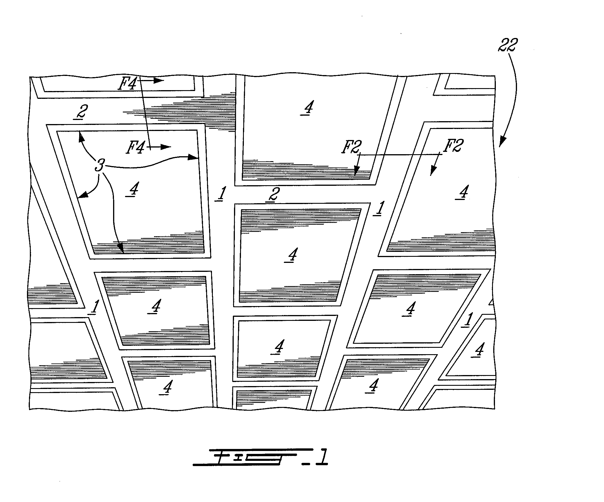
[0041]FIG. 1 illustrates a suspended ceiling 22 built with a series of main runners 1 and cross members 2 in a lattice pattern. The surface covered by the modular ceiling 22 and the distance between main runners 1 and cross members 2 can also vary in accordance with the desired visual effect. On FIG. 1 the cross members 2 are illustratively alternated on each side of the main runners 1 but they could also be aligned. Panels 4 are installed in the openings formed by the lattice of main runners 1 and cross members 2.

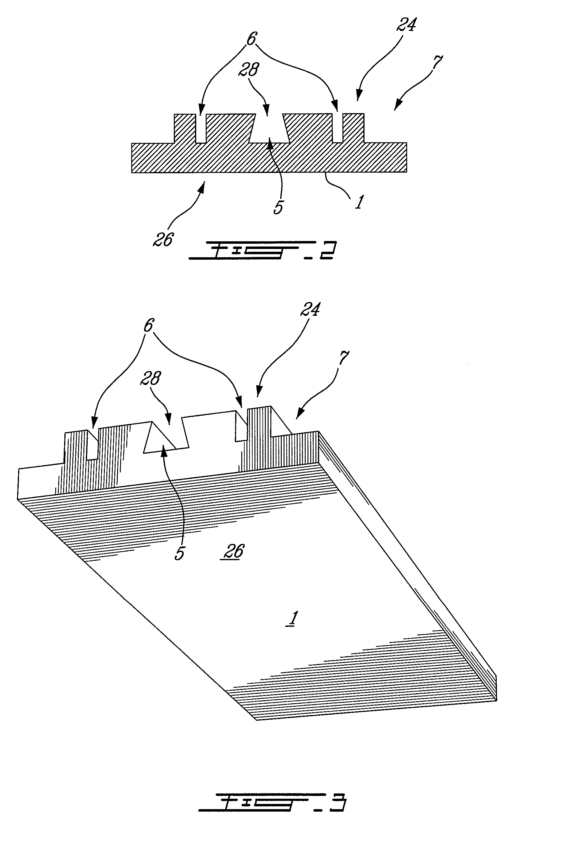
[0042]Referring to FIG. 3 and FIG. 4 it is appreciated that the main runner 1 has an upper surface 24 facing the upper side ...


PUM


Abstract

A clip assembly for use with a suspended ceiling comprises a first member secured to an overhead structural member and a second member connected to a runner supporting ceiling tiles the first and second member s being adapted to be connected together such that the runner can be suspended from the structural member via the clip assembly.

Description

CROSS-REFERENCE TO RELATED APPLICATIONS[0001]The present application claims the benefits of U.S. provisional patent application No. 61 / 202,530 filed Mar. 10, 2009, entitled SUSPENDED CEILING, which is hereby incorporated by reference.FIELD OF THE INVENTION[0002]The present invention relates to ceilings and more precisely to suspended ceilings. The invention more precisely relates to a kit of parts adapted to be assembled to form a ceiling.BACKGROUND OF THE INVENTION[0003]Suspended ceilings are usually made of a metal grid consisting of longitudinal parallel runners spaced apart from one another a desired distance and separated by cross members in a perpendicular fashion thereby creating a plurality of rectangular openings. In general, those rectangular openings are of standard sizes allowing the ventilation outlets and the lighting fixtures to be easily inserted among the ceiling panels.[0004]Suspended ceilings have been mostly utilized in office buildings and in housing basements b...

Claims


Application Information

Patent Timeline
IPC IPC(8): E04B9/22E04B9/06E04B9/18
CPCE04B9/28E04B9/22
Inventor LABONTE, PATRICKST-LAURENT, ANDRE
Owner LES PLAFONDS EMBASSY
Why Eureka
Try Eureka