Ion analysis apparatus and method of use

a technology of ion analysis apparatus and mass spectrometer, which is applied in the direction of instruments, particle separator tube details, separation processes, etc., can solve the problems of low efficiency of transmission of ions into the mass spectrometer's vacuum enclosure, limited mobility separation, and adversely affecting sampling efficiency

Active Publication Date: 2012-03-08
SHIMADZU CORP
View PDF6 Cites 43 Cited by
  • Summary
  • Abstract
  • Description
  • Claims
  • Application Information

AI Technical Summary

Benefits of technology

[0117](c) a multipole wherein a plurality of elongate electrodes are arranged circumferentially around a common axis, with the longitudinal axes of the electrodes being parallel.
[0118]A multipole is particularly preferred. Suitably the common axis of the multipole is the ion optical axis. Suitably the electrodes are arranged symmetrically around the common axis. Suitably the multipole has a circular cross section. Suitably, each electrode of the multipole is curved to accommodate the circumferential arrangement.
[0119]Preferably the differential ion mobility means comprises a waveform generator as described herein, configured to apply an asymmetric waveform to at least one electrode of the multipole. In this way, an alternating electric field is established between the electrodes. As discussed above, it is preferred that the waveform generator is configured to apply a digital waveform to at least one electrode of the multipole (suitably a voltage in response to the waveform).
[0120]Suitably the apparatus includes dipole field means for generating a dipole field with the multipole.
[0121]It is preferred that the dipole field means is the waveform generator, such that the waveform generator is configured to provide a dipole field within the multipole (i.e. within the space defined by the electrodes of the multipole). In practice, as, discussed above, a voltage in response to the waveform is applied to the multipole.
[0122]It is further preferred that the waveform generator is configured to provide an additional field, suitably a higher order field (for example a quadrupole field), within the multipole. It is preferred that a higher order field is superimposed on the dipole field. Thus, suitably, a higher order field and dipole field are applied within the space defined by the electrodes of the multipole.

Problems solved by technology

Consequently, mobility separation is limited to ions generated in atmospheric pressure ionization sources.
Atmospheric pressure IMS suffers from low efficiency of transmission of ions into the mass spectrometer's vacuum enclosure because diffusion causes expansion of the ion beam, which adversely affects sampling efficiency at the MS interface as ions must pass through a small aperture, typically 0.2 to 0.5 mm diameter.
The present inventors have found that the performance and applications of DMS so far is limited due to a number of disadvantages associated with this relatively new technology.
Nevertheless, a disadvantage of operating at a fixed flow rate is that the predetermined residence time of the ions through the DMS cannot be easily adjusted for enhancing instrument performance.
Operating the DMS at ambient or near ambient pressure and establishing high-field conditions (˜100 Td) sufficient for inducing separation requires the minimum possible separation distance between the electrodes, which in turn limits the sampling efficiency of the system and compromises sensitivity.
In particular, sampling by a MS of electrosprayed ions through the narrow gap of a DMS device becomes problematic.
This limitation is mainly imposed by the formation of bigger droplets when spraying at the higher flow rates, which, unless sufficient evaporation is allowed to occur, can significantly degrade the performance of the DMS.
Since operation of such devices at ambient conditions are incapable of attaining the desired performance, accommodation of such high flow rates required for high throughput LC MS analysis using DMS as the front-end in MS platforms remains a goal.
Furthermore, the operation of a DMS device at ambient pressure is restricted to clean samples and liquid chromatography (LC) buffers not containing involatile salts.
The direct analysis of “dirty” samples such as biological fluids can quickly compromise the DMS performance.
Robust ionization sources have been developed to tolerate these types of samples, together with the involatile buffers used in aiding LC separations, however, they remain incompatible with the DMS interface to the MS.
Another limitation of the current DMS technology is the poor resolution, measured by the peak width in terms of the compensation voltage, which is limited to ˜20 and appears to be significantly lower than that obtained in drift cell IMS.
Methods to improve resolution are compromised by the narrow range of E / N at which DMS has been operated to date.
The pressure range established in the FAIMS device is therefore limited by the operational pressure of the collision cell.
Accordingly, a range of operating pressures is not available and hence the range of accessible E / N ratios is narrow.
Thus, lowering the pressure below that studied by Nazarov et al would have an adverse affect on transport efficiency of the ions from the DMS through the inlet capillary or orifice of the MS.
Furthermore, ion transport from the DMS to the MS is inefficient.

Method used


Image

  • Ion analysis apparatus and method of use
  • Ion analysis apparatus and method of use
  • Ion analysis apparatus and method of use

Examples


Embodiment Construction

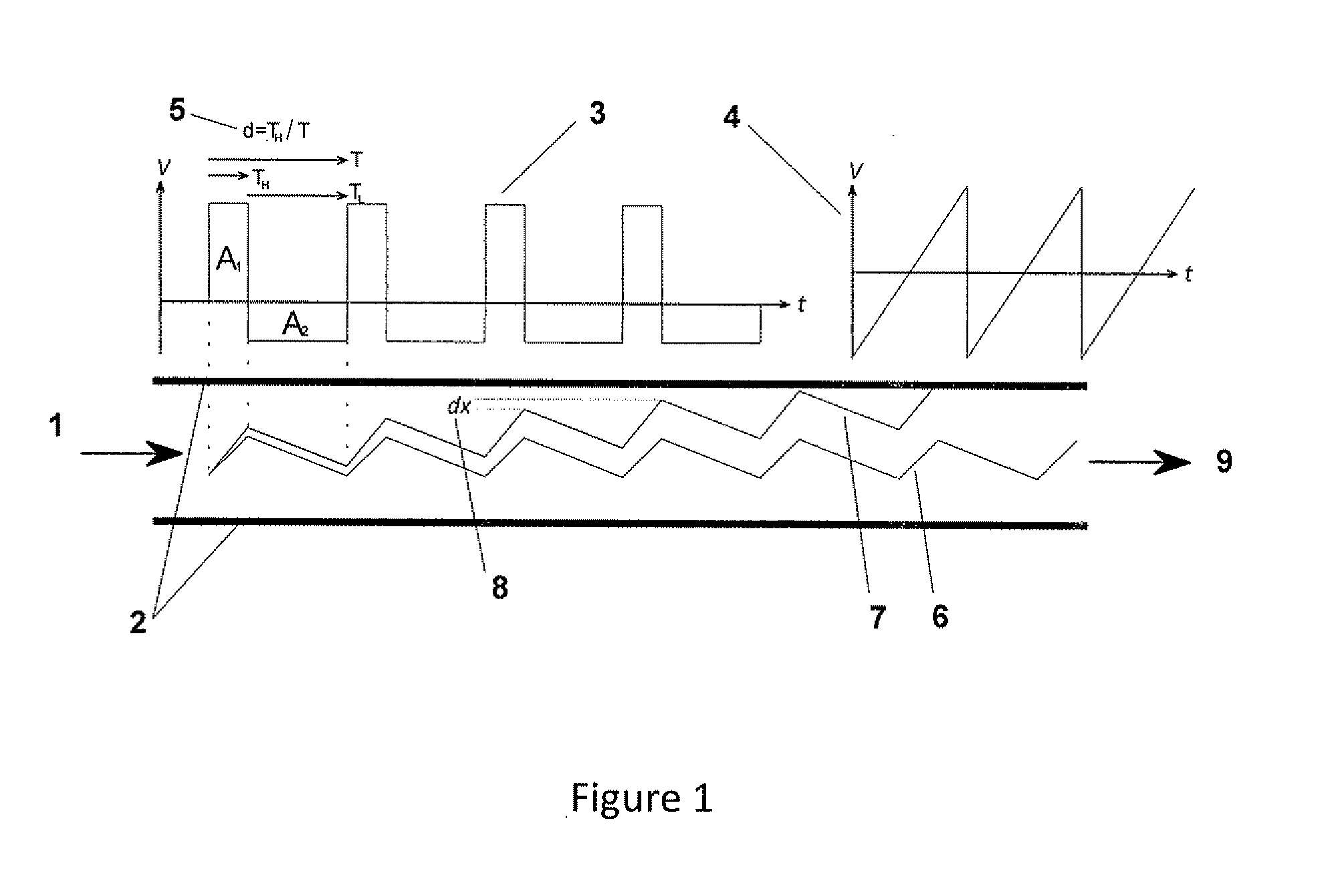
[0233]Referring to FIG. 1, shown are basic principles and the mechanism for DMS separation based on the non-linear ion mobility dependence on electric field and pressure. Ions are entrained in a gas stream 1 established between two electrodes 2. The high frequency asymmetric waveform 3 is applied to one of the two electrodes. Superimposed to the waveform is a slow compensation dc voltage 4. The frequency of the asymmetric waveform usually spans between a few hundreds of KHz to ˜1 MHz, while that of the “sawtooth” DC ramp 4 is −1.

[0234]Still referring to FIG. 1, separation of ions is possible using waveforms substantially different than the pure rectangular waveform. A family of waveforms based on quasi-sinusoidal variations of the voltage as a function of time are widely used; these are the bi-sinusoidal, the clipped sinusoidal or other substantially rectangular waveforms. Asymmetric waveforms are designed so that the area of the positive pulse matches that of the negative pulse, A1...


PUM

PropertyMeasurementUnit
frequencyaaaaaaaaaa
pressureaaaaaaaaaa
frequencyaaaaaaaaaa

Abstract

The present invention is concerned with an ion analysis apparatus for conducting differential ion mobility analysis and mass analysis. In embodiments, the apparatus comprises a differential ion mobility device in a vacuum enclosure of a mass spectrometer, located prior to the mass analyser, wherein the pumping system of the apparatus is configure to provide an operating pressure of 0.005 kPa to 40 kPa for the differential ion mobility device, and wherein the apparatus includes a digital asymmetric waveform generator that provides a waveform of frequency of 50 kHz to 25 MHz. Examples demonstrate excellent resolving power and ion transmission. The ion mobility device can be a multipole, for example a 12-pole and radial ion focusing can be achieved by applying a quadrupole field to the device in addition to a dipole field.

Description

TECHNICAL FIELD OF THE INVENTION[0001]The invention relates to differential ion mobility analysis and to mass spectrometers and in particular to the use of differential mobility spectrometry with mass spectrometry.BACKGROUND OF THE INVENTION[0002]Differential ion mobility spectrometry (DMS) is a technique based on the principles of ion mobility spectrometry (IMS). In IMS, ions are guided by an axial uniform electric field through a gas medium at constant pressure. The combined action of the driving force of the electric field accelerating the charged species and the damping force introduced by collisions between ions and the gas molecules results in an average drift velocity of the ions in the direction of the applied electric field.[0003]Ion mobility is defined as the ratio of the average drift velocity of an ion group injected into the IMS cell over the applied electric field, K=uAV / E. Therefore, the drift time of an ion through a given length is determined by the applied electric...

Claims


Application Information

Patent Timeline
Patent Type & Authority Applications(United States)
IPC IPC(8): H01J49/04H01J49/40G01N27/623
CPCG01N27/624
Inventor GILES, ROGERPAPANASTASIOU, DIMITRIS
Owner SHIMADZU CORP
Why Eureka
Try Eureka