Switch circuit

a technology of switch circuit and switch plate, which is applied in the direction of electronic switching, pulse technique, substation equipment, etc., can solve the problems of large load capacity, rising edges and falling edges, and high-frequency signals passing through the signal line for usb are more susceptible to distortion

Active Publication Date: 2012-03-08
SEMICON COMPONENTS IND LLC
View PDF6 Cites 15 Cited by
  • Summary
  • Abstract
  • Description
  • Claims
  • Application Information

AI Technical Summary

Problems solved by technology

Large load capacities can dull rising edges and falling edges.
And the high-frequency signals passing through the signal line for USB are more susceptible to distortion because of the capacity of the transistor switch inserted in the signal line for the headphone.

Method used


Image

  • Switch circuit
  • Switch circuit
  • Switch circuit

Examples


Embodiment Construction

[0020]The invention will now be described by reference to the preferred embodiments. This does not intend to limit the scope of the present invention, but to exemplify the invention.

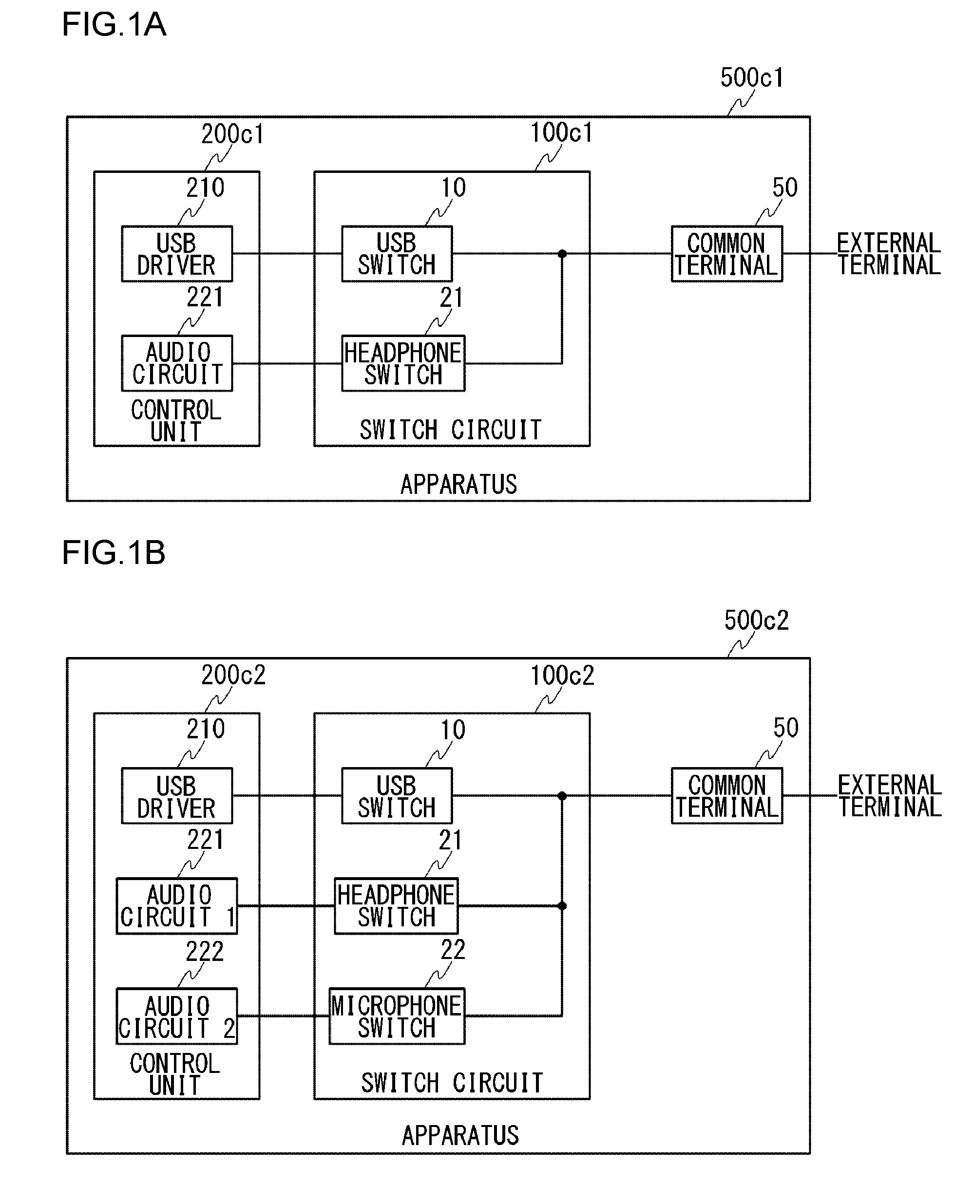
[0021]FIGS. 1A and 1B are block diagrams for use in explaining switch circuits that are to be compared with switch circuits according to an embodiment of the present invention. FIG. 1A is a block diagram for explaining a switch circuit 100c1 of comparative example 1. Note that, in this patent specification herein, a mobile phone is assumed as an apparatus 500c1. The apparatus 500c1 includes a control unit 200c1, a switch circuit 100c1, and a common terminal (port) 50. The control unit 200c1 includes a USB driver 210 and an audio circuit 221. The switch circuit 100c1 includes a USB switch 10 and a headphone switch 21.

[0022]The common terminal 50 allows insertion of a terminal of a cable for transmission of high-frequency signals (e.g., terminal of a USB cable) or insertion of a terminal of a cable dedicat...


PUM


Abstract

A signal line from a common terminal, which allows the insertion of a terminal of a cable for transmitting high-frequency signals or the insertion of a terminal of a cable dedicated to the transmission of audio signals, is branched into one line which is connected to one end of a high-frequency signal switch (USB switch) and the other line which is connected to one end of an audio signal switch (audio switch), respectively. A signal line from the other end of the high-frequency signal switch is connected to a target circuit. A signal line from the other end of the audio signal switch in a primary hierarchical position is branched into a plurality of lines, and the respective plurality of lines are connected to one end of audio signal switches (e.g., headphone switch and microphone switch) in a secondary hierarchical position. And the respective signal lines from the other end of the plurality of audio signal switches of secondary hierarchical position are connected to respective target circuits.

Description

CROSS-REFERENCE TO RELATED APPLICATIONS[0001]This application is based upon and claims the benefit of priority from the prior Japanese Patent Application No. 2010-190822, filed on Aug. 27, 2010, the entire content is incorporated herein by reference.BACKGROUND OF THE INVENTION[0002]1. Field of the Invention[0003]The present invention relates to a switch circuit to be installed within a host device.[0004]2. Description of the Related Art[0005]USB (Universal Serial Bus) is today in widespread use as a standard for connecting a computer with peripheral devices. USB is widely incorporated in stationary equipment, such as PCs, and also in mobile devices, such as mobile phones, smartphones, digital cameras, portable music players, game devices, and IC recorders.[0006]These mobile devices are provided not only with USB terminals (ports) but also with terminals (ports) for insertion of headphone terminals or earphone terminals (both hereinafter collectively referred to as “headphone termina...

Claims


Application Information

Patent Timeline
Patent Type & Authority Applications(United States)
IPC IPC(8): H03K17/687
CPCH03K17/6874H04M1/0274H03K2217/0054
Inventor YAMADA, KOUICHIMIZUKAMI, HAJIME
Owner SEMICON COMPONENTS IND LLC
Why Eureka
Try Eureka