Fuel-saving drive recommendation system and fuel-saving drive recommendation method

Active Publication Date: 2012-03-08
TOYOTA JIDOSHA KK
View PDF2 Cites 7 Cited by
  • Summary
  • Abstract
  • Description
  • Claims
  • Application Information

AI Technical Summary

Benefits of technology

[0011]The invention provides a fuel-saving drive recommendation system and fuel-saving drive recommendation method that determine whether a vehicle is in a fuel-saving drive state on the basis of a required driving force and that are able to suppress an uncomfortable feeling experienced by a driver when an automatic transmission shifts gears.
[0016]The engine rotational speed varies with the progress of shift during shifting of the automatic transmission. In the above configuration, the determination gear signal is changed on the basis of the progress of shift. Thus, it is possible to favorably change the determination gear signal.
[0019]In terms of this point, in the above configuration, a degree to which an actual input shaft rotational speed reaches the synchronous speed is calculated as the progress of shift, and the determination gear signal is changed on the basis of the calculated progress of shift. Therefore, it is possible to suppress the influence of the above described shift modes, aged degradation, or the like, on the input shaft rotational speed of the automatic transmission as much as possible when the determination gear signal is changed. Thus, when the result of determination for fuel-saving drive changes with a change of the determination gear signal, the input shaft rotational speed at the time when the result of determination changes is almost constant. By so doing, it is possible to stably suppress an uncomfortable feeling experienced by the driver.
[0023]In addition, in the above configuration, it is possible to regulate the timing, at which the determination gear signal is changed, only by changing the determination value, so it is possible to easily optimize the change timing or expand and employ the change timing to other vehicle types.
[0025]As described above, the progress of shift may be estimated on the basis of an elapsed time from when the gear instruction signal is changed. In this case, the process for changing the determination gear signal may be formed of a further simple configuration.
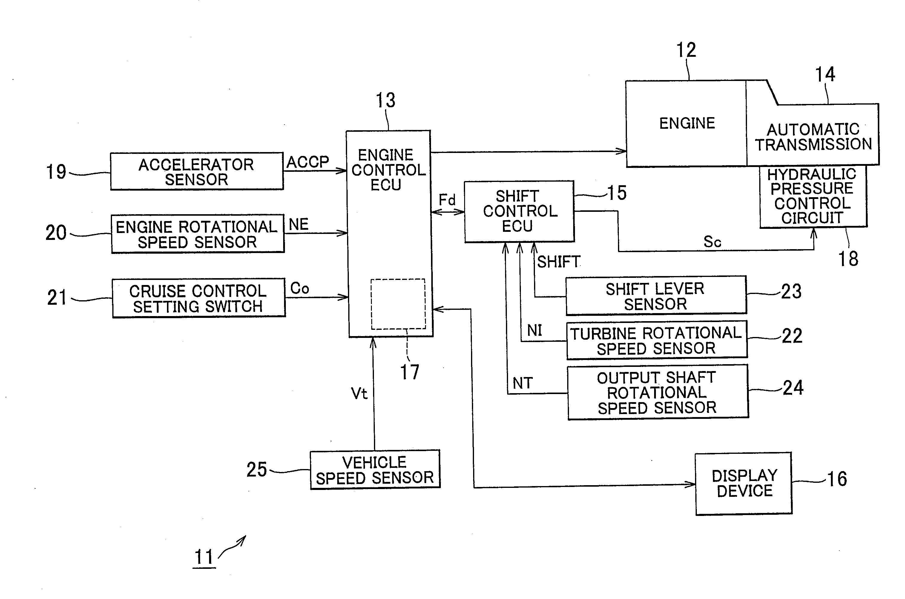
[0027]With the above configuration, the determination gear signal is changed when the shift stage of the automatic transmission is in an inertia phase, that is, when the input shaft rotational speed of the automatic transmission is varying with shift operation. Thus, the determination gear signal is changed at the time when the driver can recognize a variation in engine rotational speed, so it is possible to change the result of determination for fuel-saving drive at an appropriate timing. Incidentally, the inertia phase is formed in response to an instruction signal from a controller that controls a shift of the automatic transmission. Therefore, the above instruction signal is input to the fuel-saving drive recommendation system. By so doing, it is possible to easily determine whether the shift stage is in an inertia phase.

Problems solved by technology

Therefore, when the above required driving force is used as a determination parameter in a fuel-saving drive recommendation system mounted on a vehicle equipped for a step-gear automatic transmission, there is a possibility that a driver experiences an uncomfortable feeling when the gear is shifted because of the following reasons, for example.
Thus, there is a certain delay from when the gear instruction signal is changed to when the actual engine rotational speed varies.
However, as described above, there is a certain delay from when the gear instruction signal is changed to when the actual engine rotational speed varies.
Therefore, the driver is notified of the result of determination for fuel-saving drive ahead before the driver experiences a variation in engine rotational speed, so there is a possibility that the driver experiences an uncomfortable feeling.

Method used


Image

  • Fuel-saving drive recommendation system and fuel-saving drive recommendation method
  • Fuel-saving drive recommendation system and fuel-saving drive recommendation method
  • Fuel-saving drive recommendation system and fuel-saving drive recommendation method

Examples


Embodiment Construction

[0038]Hereinafter, an embodiment of the invention will be described with reference to FIG. 1 to FIG. 6D. A fuel-saving drive recommendation system 11 mounted on a vehicle mainly includes an engine control electronic control unit (hereinafter, referred to as engine control ECU) 13 and a transmission electronic control unit (hereinafter, referred to as shift control ECU) 15. The engine control ECU 13 controls an engine 12 mounted on the vehicle. The shift control ECU 15 controls the shift of a step-gear automatic transmission. (hereinafter, referred to as transmission) 14. An eco indicator determination unit 17 is constructed in the engine control ECU 13. The eco indicator determination unit 17 controls a display device 16. Then, the engine control ECU 13, the shift control ECU 15 and the display device 16 are communicably connected to one another via an in-vehicle network. Note that the transmission 14 is coupled to the engine 12 via a torque converter (not shown). The transmission 1...


PUM


Abstract

A fuel-saving drive recommendation system is mounted on a vehicle that includes a step-gear automatic transmission of which a gear is shifted in response to a gear instruction signal. The fuel-saving drive recommendation system calculates a required driving force based on an amount by which an output operating component is operated by a driver and a gear of the automatic transmission, makes determination for fuel-saving drive for the vehicle based on the required driving force and notifies the determination result. The fuel-saving drive recommendation system calculates a required driving force for performing output control on an engine and a required driving force for determining whether it is a fuel-saving drive state. A determination gear signal different from the gear instruction signal is used when the determination required driving force is calculated, and is changed to coincide with the gear instruction signal that has been changed.

Description

BACKGROUND OF THE INVENTION[0001]1. Field of the Invention[0002]The invention relates to a fuel-saving drive recommendation system mounted on a vehicle equipped with a step-gear automatic transmission, and also to a fuel-saving drive recommendation method.[0003]2. Description of the Related Art[0004]Some of vehicles in recent years include a fuel-saving drive recommendation system described in Japanese Patent Application Publication No. 2007-138926 (JP-A-2007-138926). In the fuel-saving drive recommendation system described in JP-A-2007-138926, a recommended region for fuel-saving drive is set on the basis of various parameters, such as engine rotational speed, intake air flow rate, vehicle speed and accelerator operation amount, and, when the actual running state of the vehicle falls within the recommended region, a lamp is turned on to notify the driver that the fuel-saving drive is achieved. On the other hand, when the actual running state of the vehicle falls outside the recomme...

Claims


Application Information

Patent Timeline
IPC IPC(8): B60W10/11B60W10/06B60W10/04B60W10/10F02D29/00F02D29/02F16H59/42F16H59/68F16H59/70F16H63/40F16H63/42F16H63/50
CPCB60L2250/16B60W10/06B60W10/11B60W30/1882B60W50/0098B60W50/14Y02T10/56B60W2510/1005B60W2540/10B60W2710/105F02D11/105F02D41/0225F02D2250/18B60W2510/0638B60W2050/146Y02T10/40Y02T10/84
Inventor NIWA, KENJISAWADA, HIROYUKI
Owner TOYOTA JIDOSHA KK
Why Eureka
Try Eureka