
Storage and transport container

a technology for storage containers and transport containers, applied in the direction of rigid containers, containers, packaging, etc., can solve the problems of insufficient carrying capacity, complicated production, and additional complexity, and achieve the effects of low weight, low cost, and low production cos

Inactive Publication Date: 2012-03-15
MONTARA VERPACKEN MIT SYST
View PDF7 Cites 7 Cited by
  • Summary
  • Abstract
  • Description
  • Claims
  • Application Information

AI Technical Summary

Benefits of technology

[0007]The object of the invention is to provide a storage and transport container that is lower in weight but that has good stability and as few projections and shoulders as possible. In addition it should be simple and cost-effective to produce.
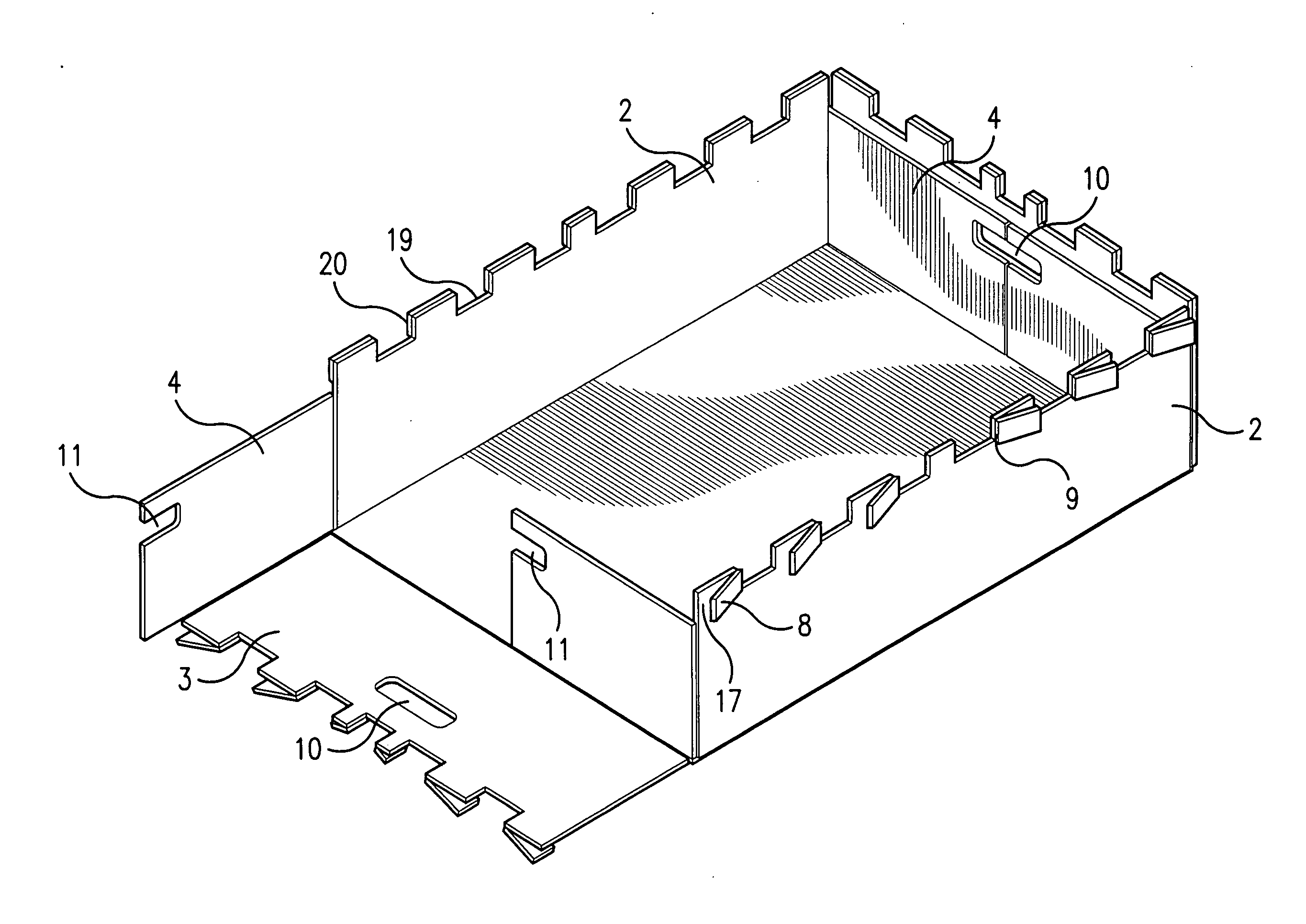
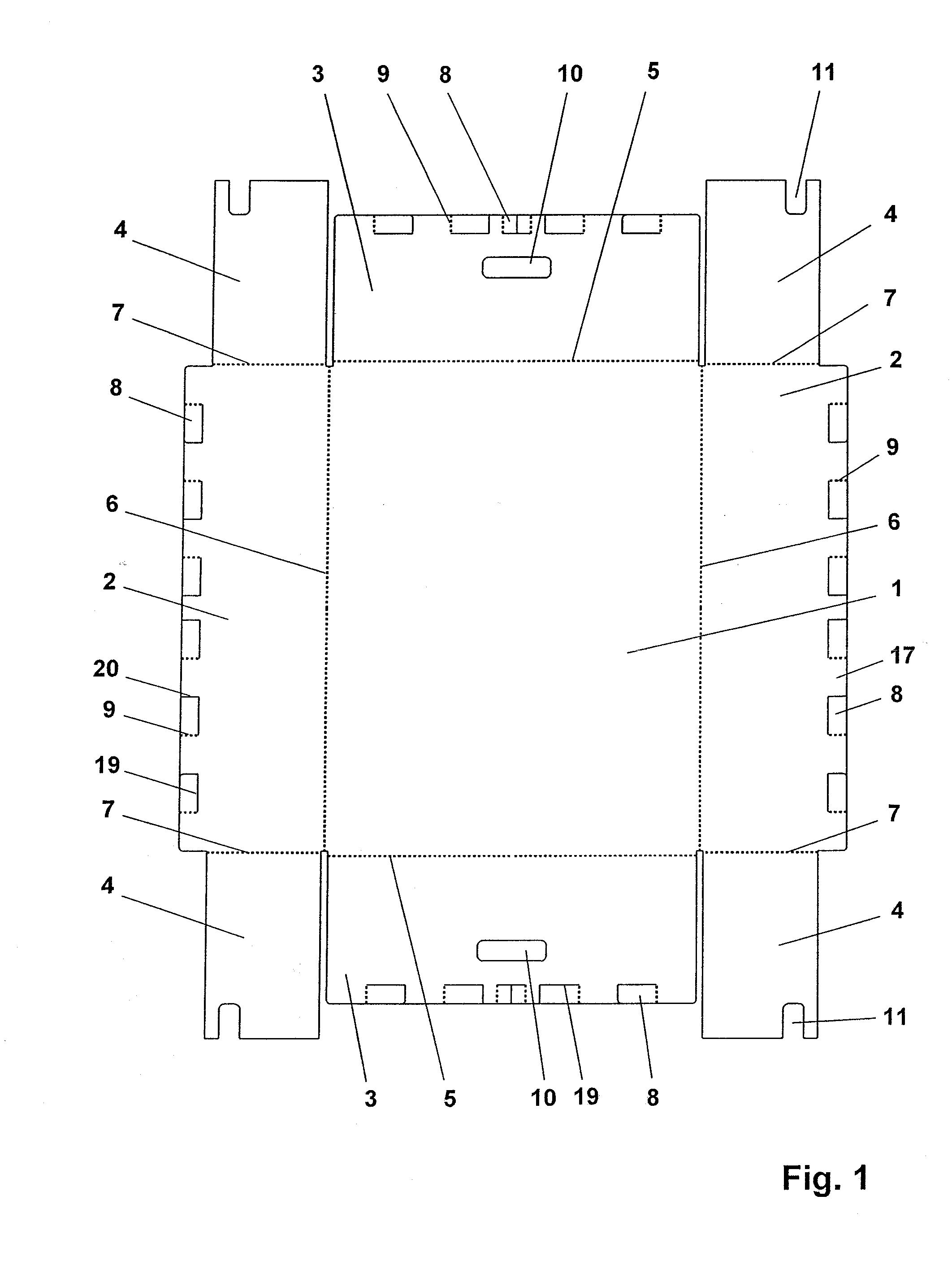
[0008]The storage and transport container comprises one integral and foldable container blank. The container blank has a bottom, two side walls that can be folded about a fold, two end walls that can be folded about a fold, and four corner flaps that can be folded inward against the side walls or end walls about a fold. In a rectangular storage and transport container, the side walls are arranged on the longer sides. When the cross-section is square, it does not matter which is called the side wall and which is called the end wall. The four corner flaps can also be disposed on the end walls. Two of the corner flaps should always advantageously be long enough that in the folded, upright condition they are equal in length to the entire side length that they cover. Consequently, they should always be arranged on the longer wall. Since this provides twice the material thickness on the end sides, it is advantageous when any grips are also provided on this side. This attains good stability and high carrying capacity.
[0011]The tabs are cut through on the lower tab edge; that is, the edge that is closest to the container bottom. Also, the tabs are cut through on one of the two vertically extending sides. The other of the two vertically extending sides is provided with a score or at least a fold so that the tabs can be folded laterally about the score, allowing for the positioning of the tabs against the intermediate pieces between the tabs. The tabs can be folded inward and outward. However, inward folding provides a container with additional complexity and disadvantages, because the container blank would first have to be turned and scored on the back side.
[0017]For a high carrying capacity, a plurality of the tabs or even all of the tabs can be joined flat to the intermediate pieces against which they are folded. This can occur for instance using an adhesive to glue the tabs to the intermediate pieces. It is particularly advantageous when the container blank comprises a thermoplastic material and the tabs are welded to the intermediate pieces. Both surfaces are exposed to hot air until their surfaces liquefy and fuse together. This produces a durable and strong connection.
[0018]It is particularly advantageous when the container blank comprises plastic hollow sheet. Plastic hollow sheet comprises two outer walls spaced from one another and ribs or honeycomb structures disposed therebetween. When using a plastic hollow sheet, the folds are added on the wall side disposed interiorly in the container and thus a target buckling point is produced. On the outside, the container is just folded at the folding points and thus closed. This results in a closed container without sharp edges.
[0019]With hollow sheets, the score is formed on the tabs in that the interior sheet wall and the ribs or honeycomb structures are cut through so that it is easy to manually fold the tabs about the lateral edge.

Problems solved by technology

In some cases, additional inserts are provided in the interior that completely line the interior without any projections, but they themselves do not have sufficient carrying capacity and they involve additional complexity.
It is complicated to produce because of the many individual parts.
The disadvantage of the aforesaid transport containers is that their production and engineering are very complex because of the thermal edges.
In addition, the complexity for the material increases because of the additional downwardly foldable tabs that are disposed along the side walls.

Method used


Image

  • Storage and transport container
  • Storage and transport container
  • Storage and transport container

Examples


Embodiment Construction

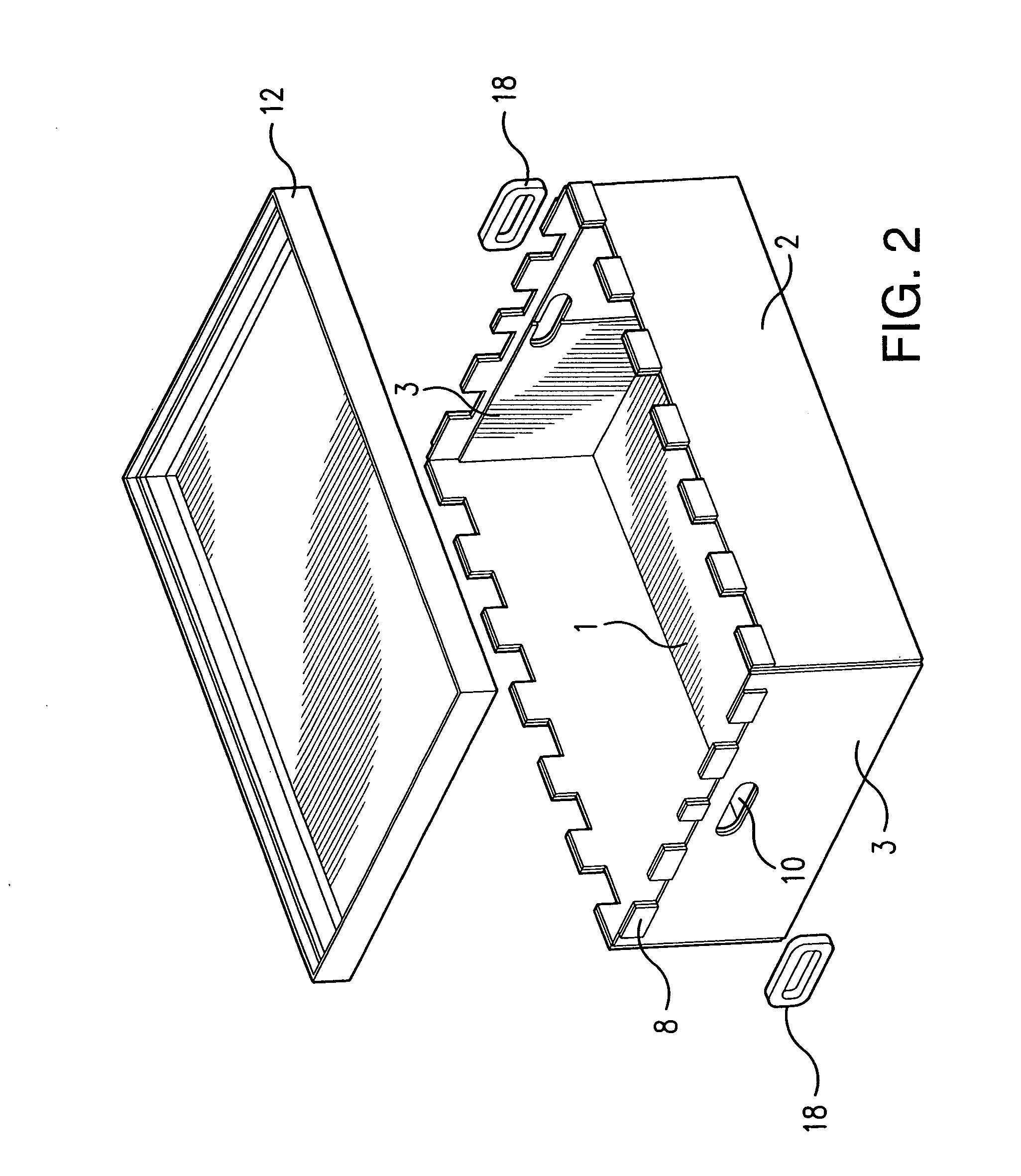
[0027]The described exemplary embodiment is a preferred variant of a container for storing and transporting small parts for automobile production. The finished storage and transport container should have a size of 800×600×250 (L×W×H in mm).

[0028]FIG. 1 is a top view of a container blank comprising a one-piece, 5-mm thick plastic hollow sheet. A contour is produced by means of a plotter, creating a bottom 1, two side walls 2 that can be folded about a fold 6, and two end walls 3 that can be folded about a fold 5. Two corner flaps 4 that can be folded inward about a fold 7 are formed on each of the two side walls 2. It is important that all of the edges are parallel. The corner flaps 4 are long enough that when they are folded in the assembled condition they cover the width of the end wall 3. There are notches 11 on the corner flaps 4 for grips 18 that can be inserted later. Grip openings 10 are also included in each of the two end walls 3. The folds 5, 6, 7 are also added in using th...


PUM


Abstract

Provided is a stackable storage and transport container for storing and for single-use or multiple-use transport of goods, especially small parts.The container is assembled from a foldable container blank having a bottom, two side walls foldable about a fold, two end walls foldable about a fold, and four corner flaps foldable inward against the side walls or end walls about a fold. Tabs are formed on the side walls and end walls such that they can fold laterally against the intermediate pieces. A stackable profile having a hook edge is placed about the upper edge to provide for the stacking of a number of containers. The container blank preferably is made of a plastic hollow sheet.

Description

BACKGROUND OF THE INVENTION[0001]The invention relates to a stackable storage and transport container for storing and for single-use or multiple-use transport of goods of all types, especially small parts.[0002]Cargo containers are particularly used as transport and storage containers when tools or components for a manufacturing process must be transported or placed in temporary storage. They generally comprise sheet metal or plastic sheets that can be joined to one another by gluing, welding, or in a positive fit. In addition to having adequate carrying capacity and service life, it is also important that, to the extent possible, the containers have no projections or shoulders that can constrict the interior, or otherwise present other obstructions. In some cases, additional inserts are provided in the interior that completely line the interior without any projections, but they themselves do not have sufficient carrying capacity and they involve additional complexity.[0003]EP 0 674...

Claims


Application Information

Patent Timeline
Patent Type & Authority Applications(United States)
IPC IPC(8): B65D21/00
CPCB65D11/1833
Inventor LOHSE, UWE
Owner MONTARA VERPACKEN MIT SYST
Learn More