Hanging structure

a technology of hanging structure and mounting rack, which is applied in the direction of building scaffolds, machine supports, other domestic objects, etc., can solve the problems of affecting the interior design, the bulkyness of the tv cabinet, and the inability to properly hang the electronic equipment without the mounting rack

Inactive Publication Date: 2012-03-15
HANNSPREE INC
View PDF7 Cites 9 Cited by
  • Summary
  • Abstract
  • Description
  • Claims
  • Application Information

AI Technical Summary

Benefits of technology

[0014]According to the present invention, the bezel recess may be recessed with a second guiding path at side face, and the ear-shaped hanging part may include a protrusion at outer surface of the tubular body movably arranged in the second guiding path. The second guiding path includes a guiding groove and a positioning slot which are communicated with each other. When the protrusion moves into the guiding groove, the ear-shaped hanging part extends out of the bezel recess and the first hanging member is rotatable. When the protrusion moves into the positioning slot, rotation of the first hanging member is restrained.
[0015]The first hanging member may further include a shaft member and a locking part, and that the bezel recess, at bottom face, is provided with a through hole. The ear-shaped hanging part, the shaft member, and the locking part are connected in orderly manner and the shaft member passes through the through hole. In such configuration, when the ear-shaped hanging part extends out of the bezel recess, the locking part axially locks at the back bezel for preventing the first hanging member from escaping far away from the bezel recess.

Problems solved by technology

Large TV set occupies a large space in a room, and a TV cabinet is bulky and often affects the interior design.
Obviously, the electronic apparatus is unable to be hung properly without the mounting rack.

Method used


Image

  • Hanging structure
  • Hanging structure
  • Hanging structure

Examples


Embodiment Construction

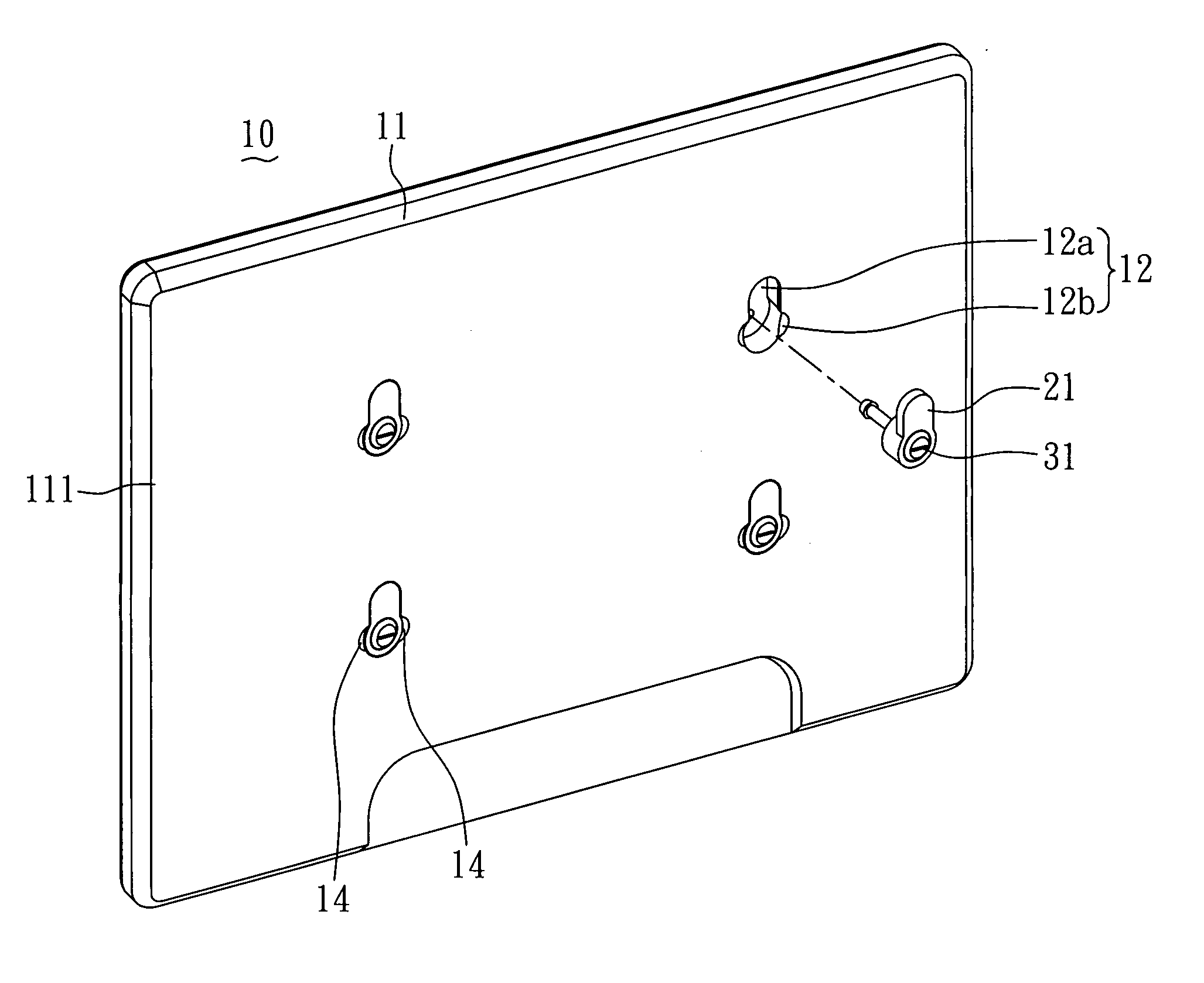
[0032]Referring to FIG. 3, a perspective view illustrating a hanging structure installed in a display according to an embodiment of the present invention; and FIG. 4, an exploded view of the hanging structure in FIG. 3; an LCD display 10 is shown and has four sets of hanging structures installed on a back bezel 11, each hanging structure comprising a first hanging member 21 and a second hanging member 31. The back bezel 11, at a portion of its outer surface 111, is recessed with a bezel recess 12 in which the first hanging member 21 is movably arranged inside. The second hanging member 31 is movably arranged in the first hanging member 21. The bezel recess 12 is divided into an upper recess 12a and a lower recess 12b.

[0033]The first hanging member 21 includes an ear-shaped hanging part 22, a shaft member 23, and a locking member 24 which are sequentially connected. The bezel recess 12 of the back bezel 11 is provided with a through hole 123 at a bottom face 121 for communicating an...


PUM


Abstract

A hanging structure includes a back bezel recessed with a bezel recess, a first hanging member, and a second hanging member. The first hanging member movably arranged in the bezel recess includes an ear-shaped hanging part which is axially recessed with an accommodating hole with a first guiding path at side face. The first guiding path includes an axial segment and two positioning notches obliquely extending from the axial segment. The second hanging member movably arranged in the accommodating hole includes a main body and a mushroom-shaped hanging part. The main body, at its surface, includes a guiding protrusion which is movably arranged in the first guiding path of the first hanging member. The mushroom-shaped hanging part selectively extends out of the accommodating hole depending on which positioning notch the guiding protrusion moves into. Therefore, the hanging structure has various hanging modes to be selected.

Description

BACKGROUND OF THE INVENTION[0001]1. Field of the Invention[0002]The present invention relates to a hanging structure, and more particularly, to a hanging structure for an electronic apparatus such as an LCD display.[0003]2. Description of Related Art[0004]In the past when people purchase television (TV) sets, the size of the TV screen was the main consideration. Large TV set occupies a large space in a room, and a TV cabinet is bulky and often affects the interior design. With the advance of the technology, electronic devices have become thinner and lighter. This is also true for home appliances. For instance, nowadays the flat displays such as LCD TVs, LED TVs, plasma TVs and the like have been introduced to the market. The TV set has led this trend.[0005]With the introduction of the flat display TV, the TV set no longer is limited to being placed on a TV cabinet. It can now be matched with the interior design, and be set in or hung on a wall. Reference to a hanging apparatus for h...

Claims


Application Information

Patent Timeline
Patent Type & Authority Applications(United States)
IPC IPC(8): H05K7/14
CPCF16M13/02
Inventor HUANG, WEN-HUNGTSAI, STEPHEN
Owner HANNSPREE INC
Why Eureka
Try Eureka