
Image processing devices and sheet feeding devices

a technology of image processing device and feeding device, which is applied in the direction of thin material processing, article separation, printing, etc., can solve the problems of feeding failure and placing the document out of position with resp

Active Publication Date: 2012-03-15
BROTHER KOGYO KK
View PDF31 Cites 2 Cited by
  • Summary
  • Abstract
  • Description
  • Claims
  • Application Information

AI Technical Summary

Benefits of technology

The present invention provides an image processing device and sheet feeding device that can overcome issues caused by differences in roller speed. The device includes a first feeding unit and a second feeding unit that feed sheets simultaneously, reducing feeding failures and improving image quality. The device also includes a reference member that helps stabilize the sheet during processing. The technical effects of the invention include improved image quality, reduced feeding failures, and improved stability of the sheet during processing.

Problems solved by technology

As a result, a feeding failure occurs and places the document out of position with respect to the feeding direction.
The above problems occur on small-diameter rotating shafts used to reduce the weight of the sheet feeding devices.
The problems also occur on image reading devices having auto document feeders (ADF) that feed large-sized documents, such as A3 size, or on inkjet-type image recording apparatuses configured to record an image on large-size recording sheets, such as size A3, because the amount of flexing of rotating shafts 211 and 212 increases in these devices.

Method used


Image

  • Image processing devices and sheet feeding devices
  • Image processing devices and sheet feeding devices
  • Image processing devices and sheet feeding devices

Examples


Embodiment Construction

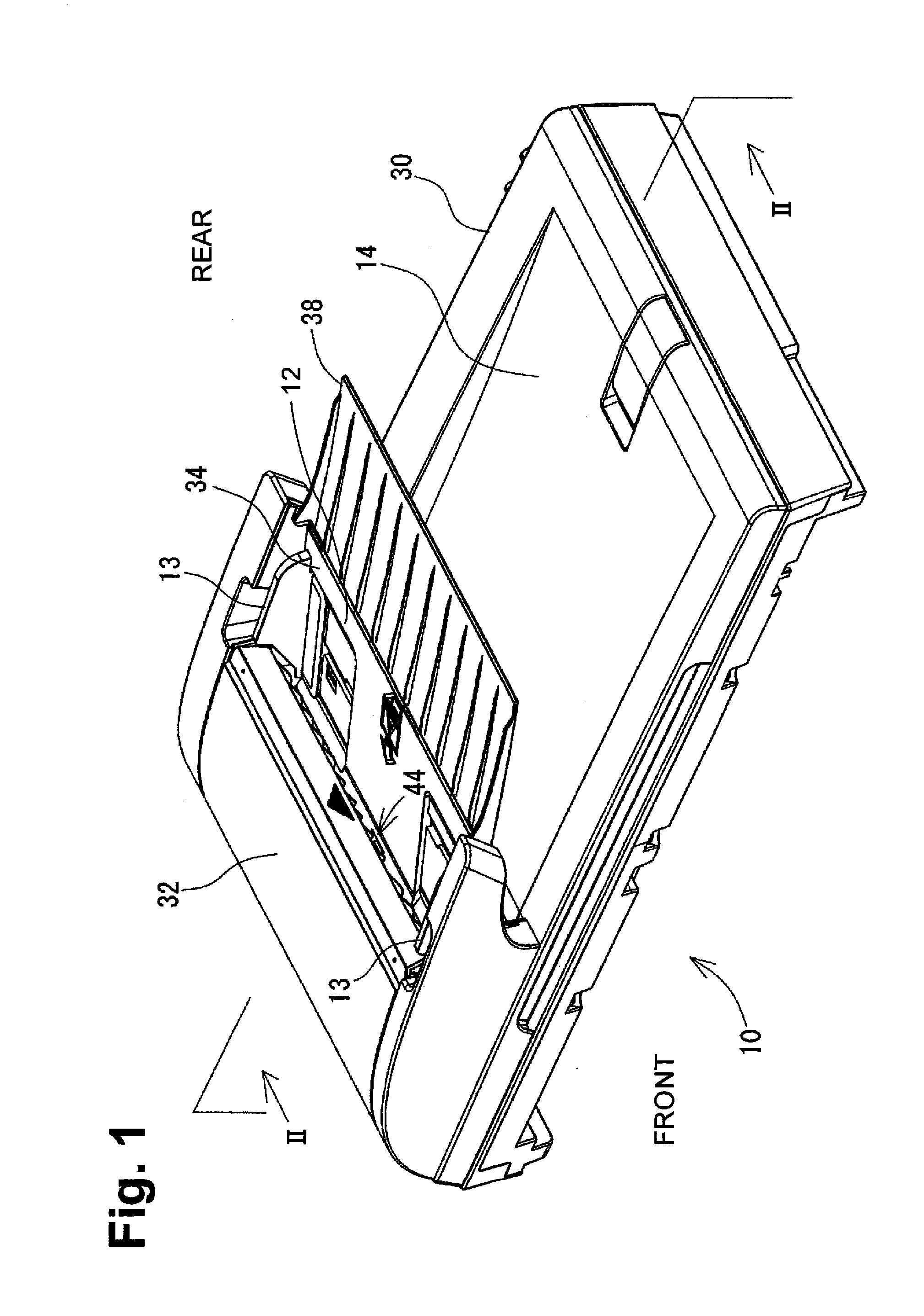
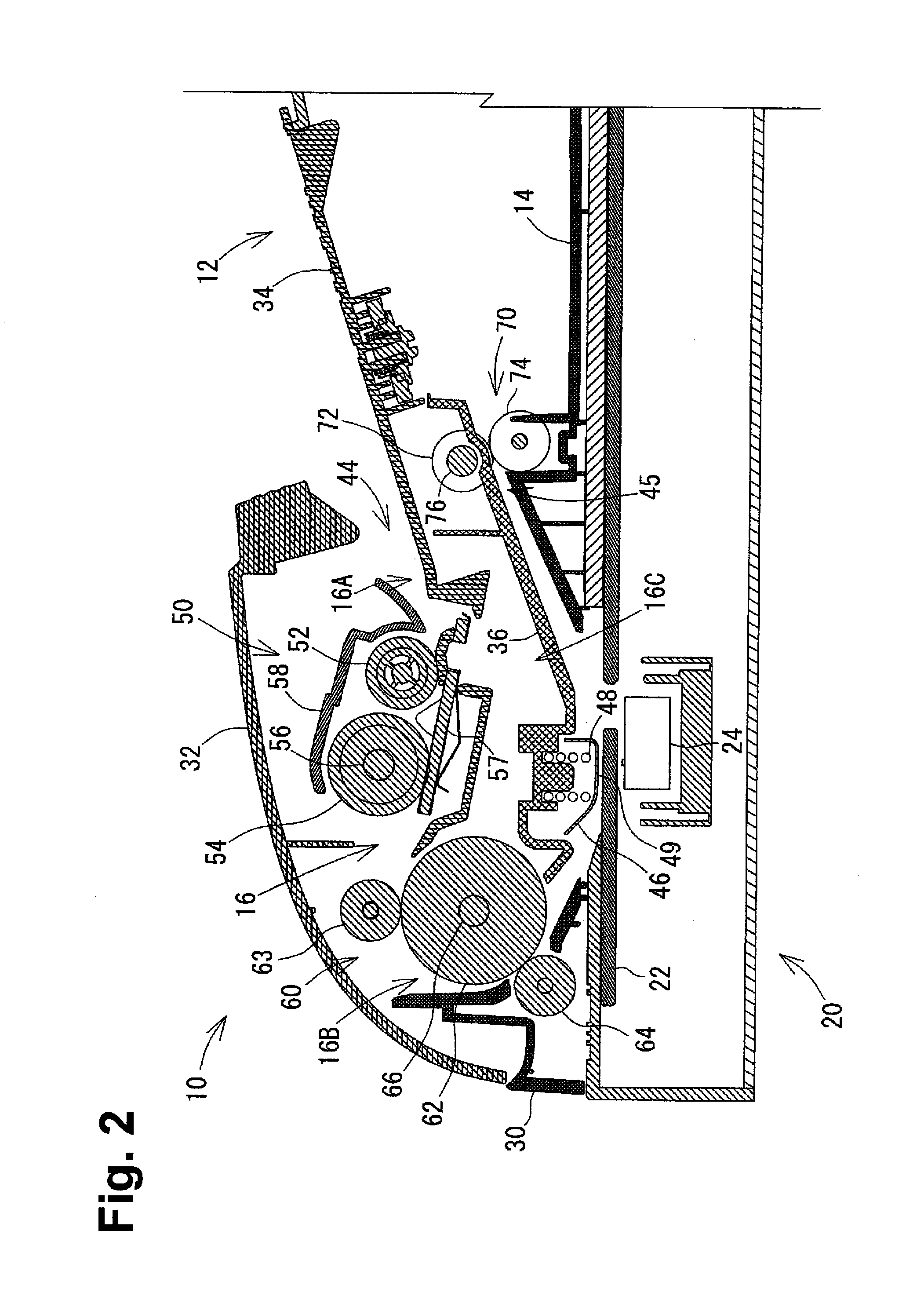
[0039]Embodiments of the present invention and their features and technical advantages may be understood by referring to FIGS. 1-14, like reference numerals being used for like corresponding portions in the various drawings.

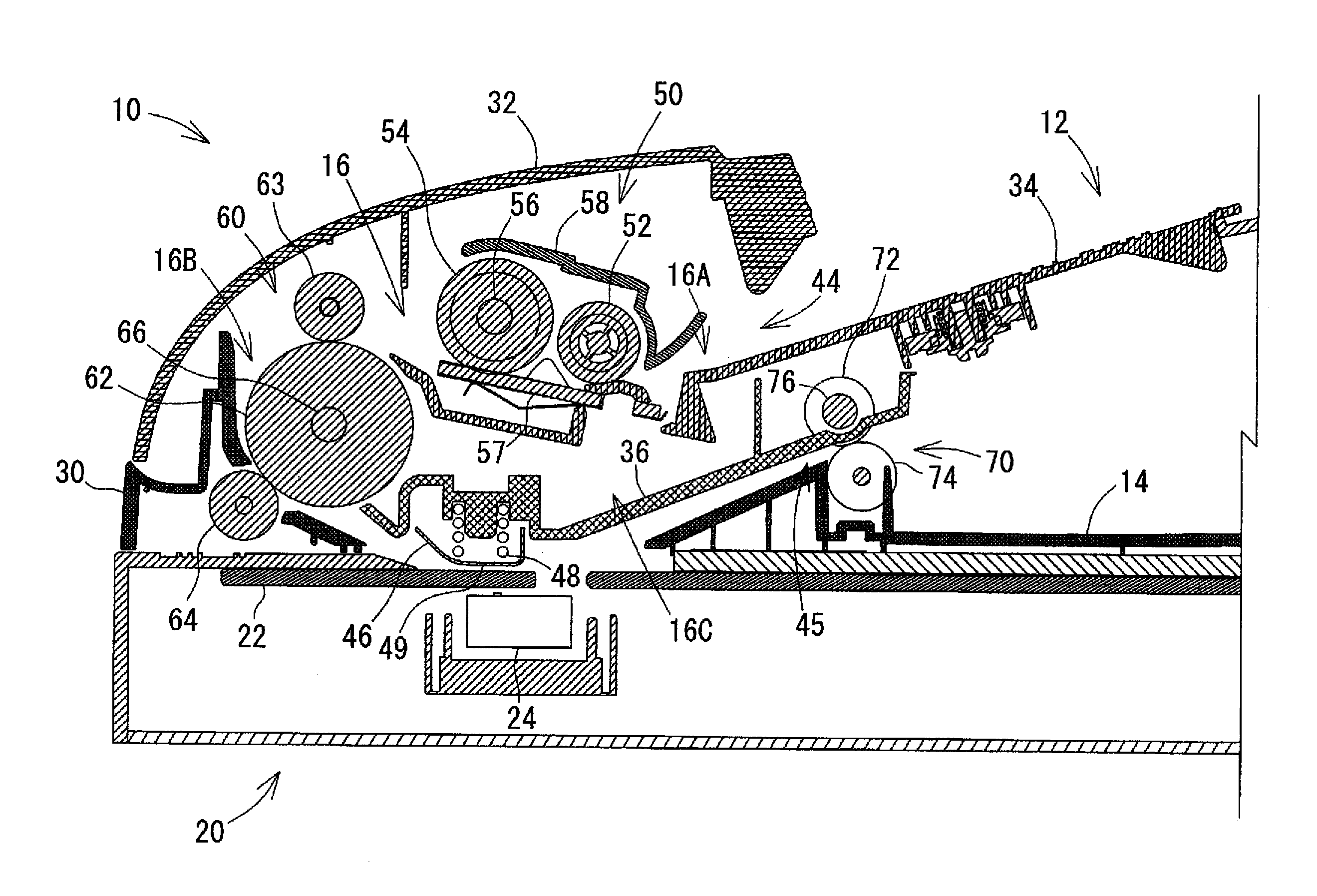
[0040]An automatic document feeder (ADF) 10 may be configured to feed sheets, e.g., documents and recording mediums, along a feeding path 16. Referring to FIG. 1, ADF 10 may comprise a document tray 12 for loading documents and an output tray 14 for outputting documents. Referring to FIG. 2, an interior of ADF 10 may comprise feeding path 16. ADF 10 automatically and continuously may feed documents in a feeding direction from document tray 12 to output tray 14 via feeding path 16. ADF 10 may be disposed on an image processing device 20, e.g., an image reading device.

[0041]Image processing device 20 may comprise a contact glass 22 disposed at an upper portion of image processing device 20 and an image processing portion 24, e.g., an image sensor. Image processing ...


PUM


Abstract

An image processing device includes first and second feeding units. The first feeding unit feeds a sheet toward the second feeding unit in a sheet feeding direction via a sheet feeding path. The device further includes an image processing portion. The first feeding unit is in the path upstream of the processing portion and includes a first shaft rotating in the feeding direction. The second feeding unit is in the path downstream of the processing portion, and the first and the second units feed and hold the sheet. The second feeding unit includes a second shaft rotating in the feeding direction. The device includes a first supporting member supporting first and second ends of the first shaft, a second supporting member supporting first and second ends of the second shaft, and a third supporting member supporting one shaft at a predetermined portion which is not either end of either shaft.

Description

CROSS REFERENCE TO RELATED APPLICATION[0001]The present application claims priority from Japanese Patent Application No. 2007-340874, which was filed on Dec. 28, 2007, the disclosure of which is incorporated herein by reference in its entirety.BACKGROUND OF THE INVENTION[0002]1. Field of the Invention[0003]The present invention relates to image processing devices comprising a sheet feeding device configured to feed sheets, such as documents and recording mediums, using a plurality of rollers.[0004]2. Description of Related Art[0005]Known scanners, facsimile machines, and copiers, and multifunction devices configured to perform the functions of a scanner, a facsimile machine, and a copier, such as the devices described in U.S. Pat. No. 7,080,836 B2 and Japanese Laid-Open Patent Publication Nos. 9-238236 and 5-155459, include a sheet feeding device that automatically feeds documents stored in a document tray, one by one, to a reading position, or automatically feeds recording mediums ...

Claims


Application Information

Patent Timeline
Patent Type & Authority Applications(United States)
IPC IPC(8): B65H3/06
CPCH04N1/0057H04N1/00588H04N1/00591H04N2201/0081H04N1/12H04N1/193H04N1/00602B65H5/062B41J11/007B65H2404/1341B65H2801/06
Inventor OSAKABE, YOSHINORINAKAKITA, SATORU
Owner BROTHER KOGYO KK
Learn More