
Egress lighting for two module luminaires

a technology of egress lighting and luminaires, which is applied in the direction of lighting applications, lighting support devices, and with built-in power, etc., can solve the problems of poor uniformity along shelves or racks, less than ideal light delivery efficiency, and product quality is far from ideal

Active Publication Date: 2012-03-15
ABL IP HLDG
View PDF2 Cites 63 Cited by
  • Summary
  • Abstract
  • Description
  • Claims
  • Application Information

AI Technical Summary

Benefits of technology

[0006]Embodiments of the present invention are directed toward various aspects of a linear light fixture. In some embodiments, a linear rail and node lighting system is disclosed. In some embodiments, rails can include a plurality of discreet light sources that are disposed along the length of the rail. An elongated optical element can be included within the rail that can provide a photometric distribution tailored toward aisle and shelf applications according to some embodiments. In some embodiments, the node can include control, external sensing, power, and/or communication circuitry. Nodes can, but do not have to, communicate and/or share power between each other through communication and/or power channels within the rails.
[0007]The terms “invention,”“the invention,”“this invention” and “the present invention” used in this patent are intend...

Problems solved by technology

The size of the fluorescent source however, can result in less than ideal light delivery efficiency and top to bottom uniformity on the racks.
The relatively small size of these lamps coupled with their high light output, however, can often result in glare.
These highbays typically have an axially symmetric photometric distribution which, when coupled with distant fixture spacing, leads to poor uniformity along shelves or racks.
While sometimes achieving improved photometric performance, these products are far from ideal.
The size of fluorescent lamps makes it relatively inefficient to control their luminous output in the along dimension.
When mounted discretely, this lack of optical control leads to the same illuminance uniformity problem along the racks suffered by HID highbays.
If mounted in something closer to an end-to-end format, their size and weight present an added burden from an installation standpoint and typically to the purchase price as well.

Method used


Image

  • Egress lighting for two module luminaires
  • Egress lighting for two module luminaires
  • Egress lighting for two module luminaires

Examples


Embodiment Construction

[0041]The subject matter of embodiments of the present invention is described here with specificity to meet statutory requirements, but this description is not necessarily intended to limit the scope of the claims. The claimed subject matter may be embodied in other ways, may include different elements or steps, and may be used in conjunction with other existing or future technologies. This description should not be interpreted as implying any particular order or arrangement among or between various steps or elements except when the order of individual steps or arrangement of elements is explicitly described.

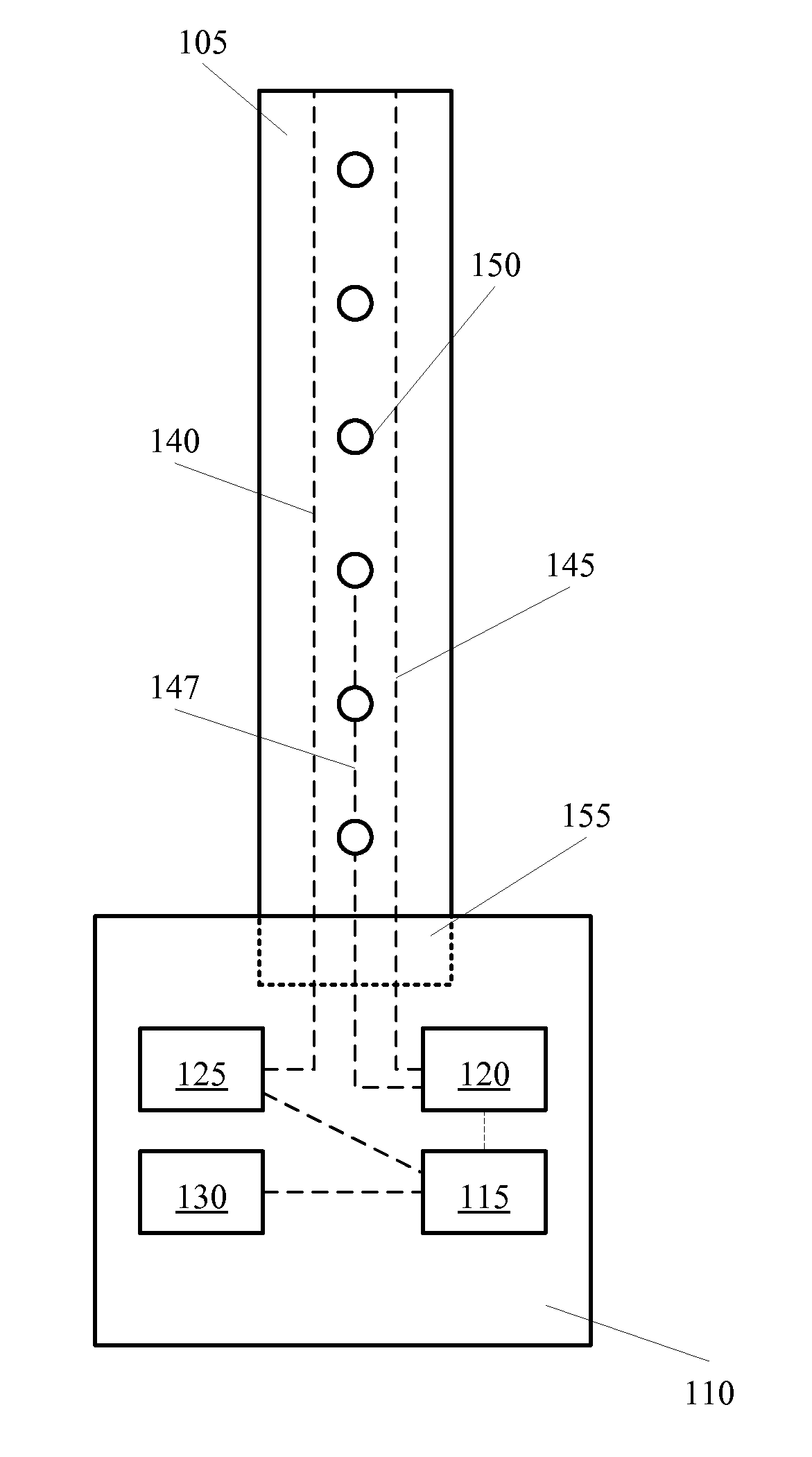
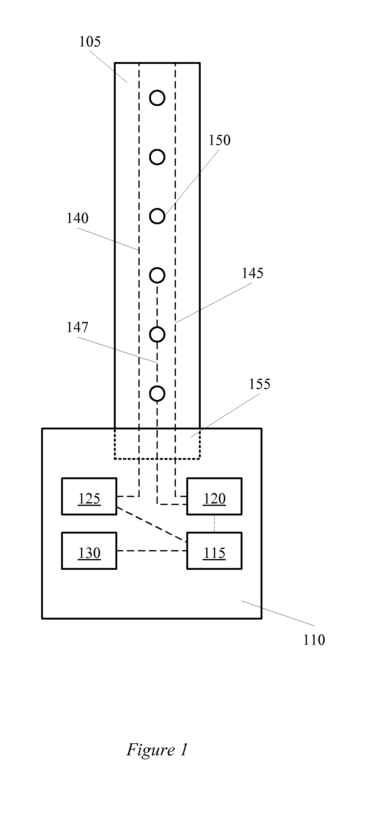
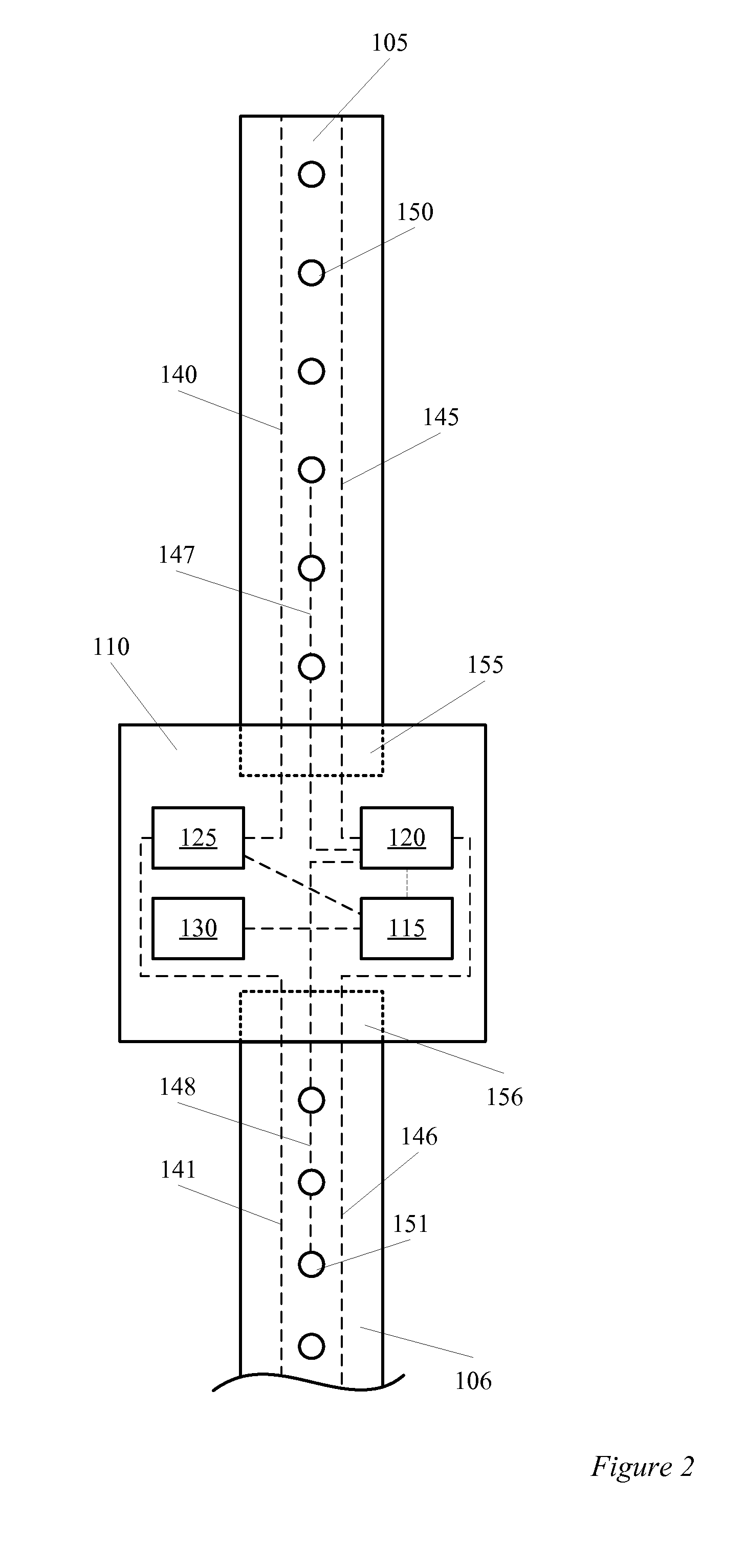
[0042]Embodiments of the present invention are directed toward various aspects of a linear light fixture. In some embodiments, a linear rail and node lighting system is disclosed. In some embodiments, rails can include a plurality of discreet light sources that are disposed along its length. An elongated optical element may be provided that can impart a photometric distribution ...


PUM


Abstract

Embodiments of the invention provide for a lighting system for illuminating aisles with shelving. A rail can include a plurality of LEDs that extend along the length of the rail. The rail can be coupled with a node that includes various components along with an egress light source. The LEDs can be used to primarily illuminate the shelving on both or one side of the aisle. The egress light can be used to illuminate the aisle during times of emergency, at night, or when egress may be required.

Description

CROSS-REFERENCES TO RELATED APPLICATIONS[0001]This application is a continuation-in-part of U.S. patent application Ser. No. 13 / 173,788, filed Jun. 30, 2011 and entitled “Linear Light Fixtures,” which claims the benefit of commonly assigned U.S. Provisional Application No. 61 / 360,156, filed Jun. 30, 2010 and entitled “Project Ion,” the entirety of each of which is incorporated herein by reference for all purposes.BACKGROUND[0002]One common way to light warehouse storage racks is with linear fluorescent lamps mounted end to end. These linear devices are a natural fit for aisle applications in terms of the uniformity of illumination along the length of the aisle and shadow reduction. The size of the fluorescent source however, can result in less than ideal light delivery efficiency and top to bottom uniformity on the racks. Instead, the shelves are typically lit brighter at the top and dimmer at the bottom.[0003]Another way to light warehouse storage racks is with high intensity disch...

Claims


Application Information

Patent Timeline
IPC IPC(8): F21V21/00H05B44/00
CPCF21S2/005Y10S362/80F21Y2101/02F21W2111/06F21V33/0076F21V33/0052F21V29/004F21V27/00F21V15/015F21V15/013F21V7/0091F21V5/04F21S9/022F21S4/008F21Y2103/003F21V23/0442F21V15/012F21V29/20F21V29/507F21V29/74H05B33/0803F21S4/28F21Y2103/10F21Y2115/10H05B45/30
Inventor LEADFORD, KEVIN FRANKLINGOULD, CARLNELSON, PETER K.
Owner ABL IP HLDG
Features
  • Generate Ideas
  • Intellectual Property
  • Life Sciences
  • Materials
  • Tech Scout
  • Unparalleled Data Quality
  • Higher Quality Content
  • 60% Fewer Hallucinations
Learn More