

Unprepared Cable End Coaxial Connector
- Summary
- Abstract
- Description
- Claims
- Application Information
AI Technical Summary
Benefits of technology
Problems solved by technology
Method used
Image

Examples
Embodiment Construction
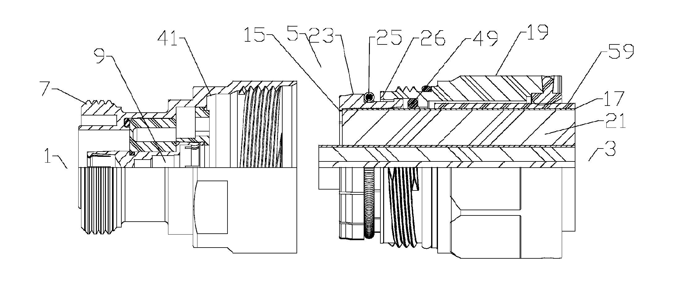
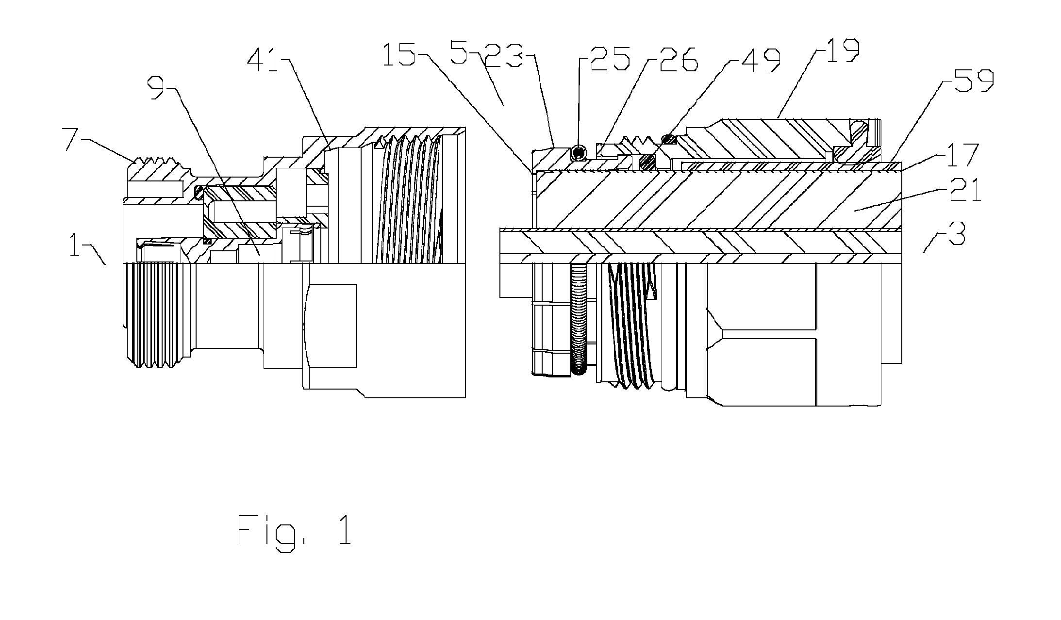
[0038]One skilled in the art will appreciate that the connector end 1 and the cable end 3 are descriptors used herein to clarify longitudinal locations and / or contacting interrelationships between the various elements of the coaxial connector(s). In addition to the identified positions in relation to adjacent elements along the coaxial connector 5 longitudinal axis, each individual element has a connector end side and a cable end side, i.e. the sides of the respective element that are facing the respective connector end 1 and the cable end 3 of the coaxial connector 5.
[0039]A first embodiment of a coaxial connector, as shown in FIGS. 1-5, includes a connector body 7 provided with a connector body bore 9. As best shown in FIG. 1, a compression sidewall 41 provided in the connector body bore has an increasing diameter towards the cable end 3. A coupling body 19 provided with a coupling body bore 21 is coupled to the connector body 7 via thread(s) 47.
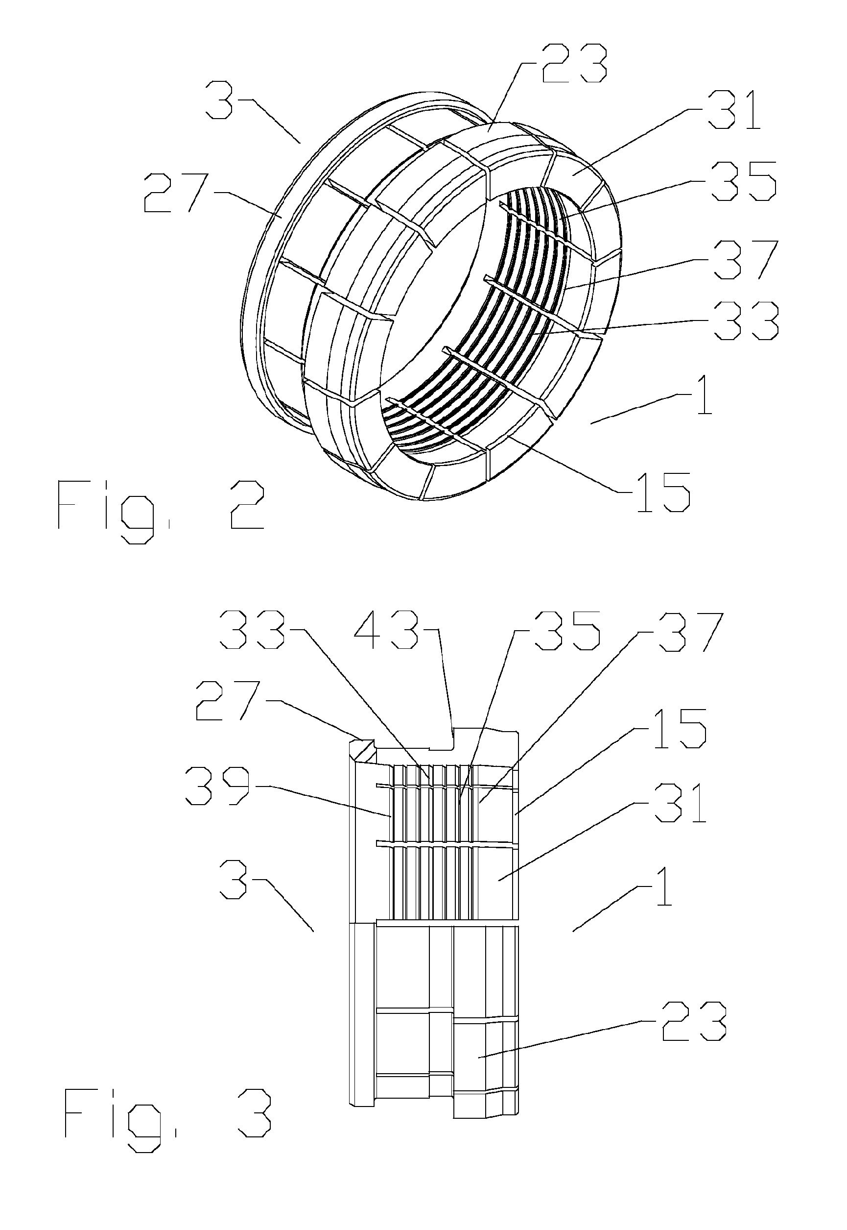
[0040]A grip ring 23, best shown in...
PUM
 Abstract
Description
Claims
Application Information