Monitoring of the position of a pipe inspection tool in a pipeline

Active Publication Date: 2012-03-22
SCHLUMBERGER TECH CORP
View PDF6 Cites 16 Cited by
  • Summary
  • Abstract
  • Description
  • Claims
  • Application Information

AI Technical Summary

Benefits of technology

[0013]The plurality of acoustic sensors are preferably in the form of one or more arrays.

Problems solved by technology

However, in both of these patent applications, all the sensing is within the pig itself.

Method used


Image

  • Monitoring of the position of a pipe inspection tool in a pipeline
  • Monitoring of the position of a pipe inspection tool in a pipeline
  • Monitoring of the position of a pipe inspection tool in a pipeline

Examples


Embodiment Construction

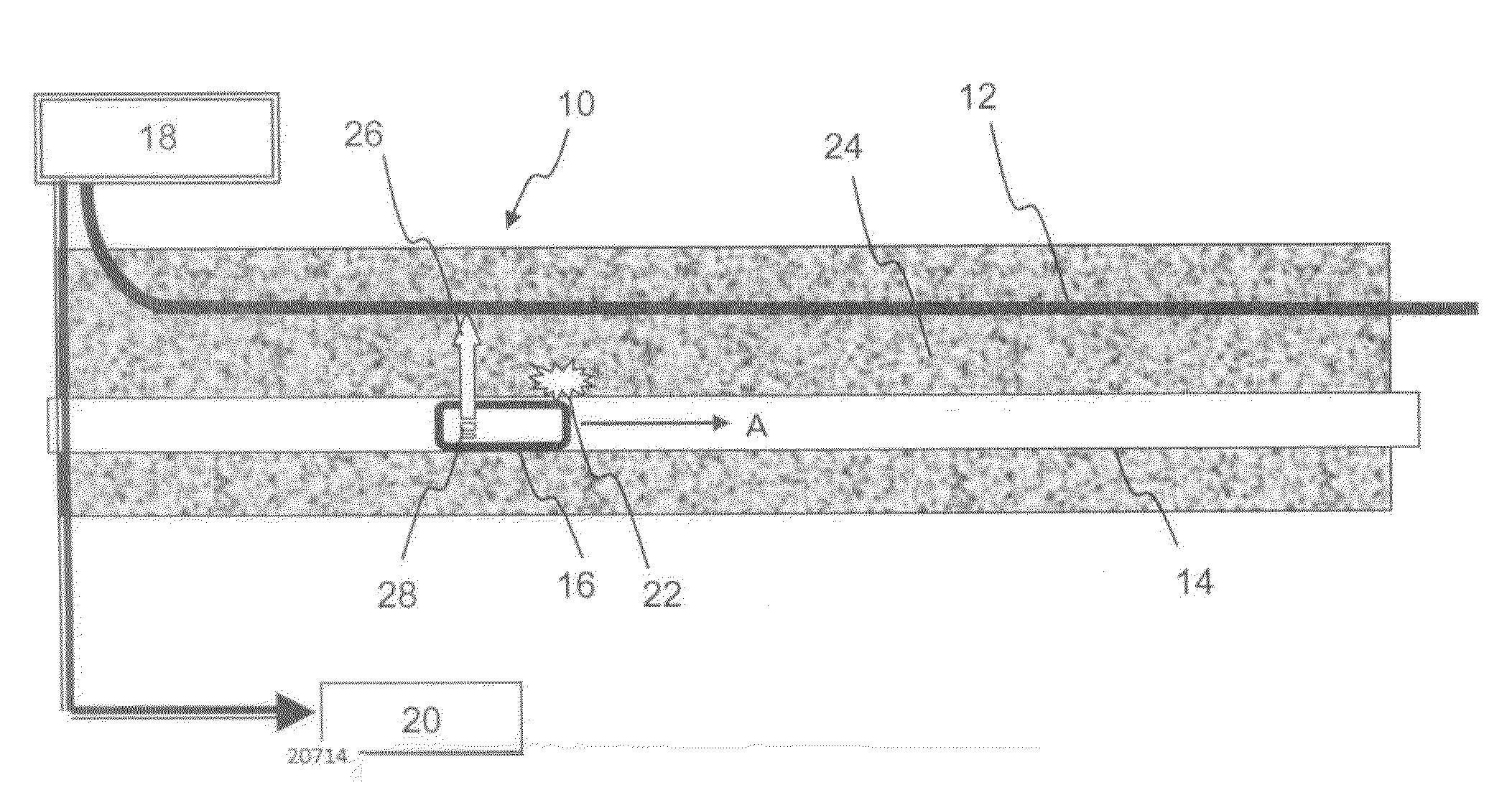
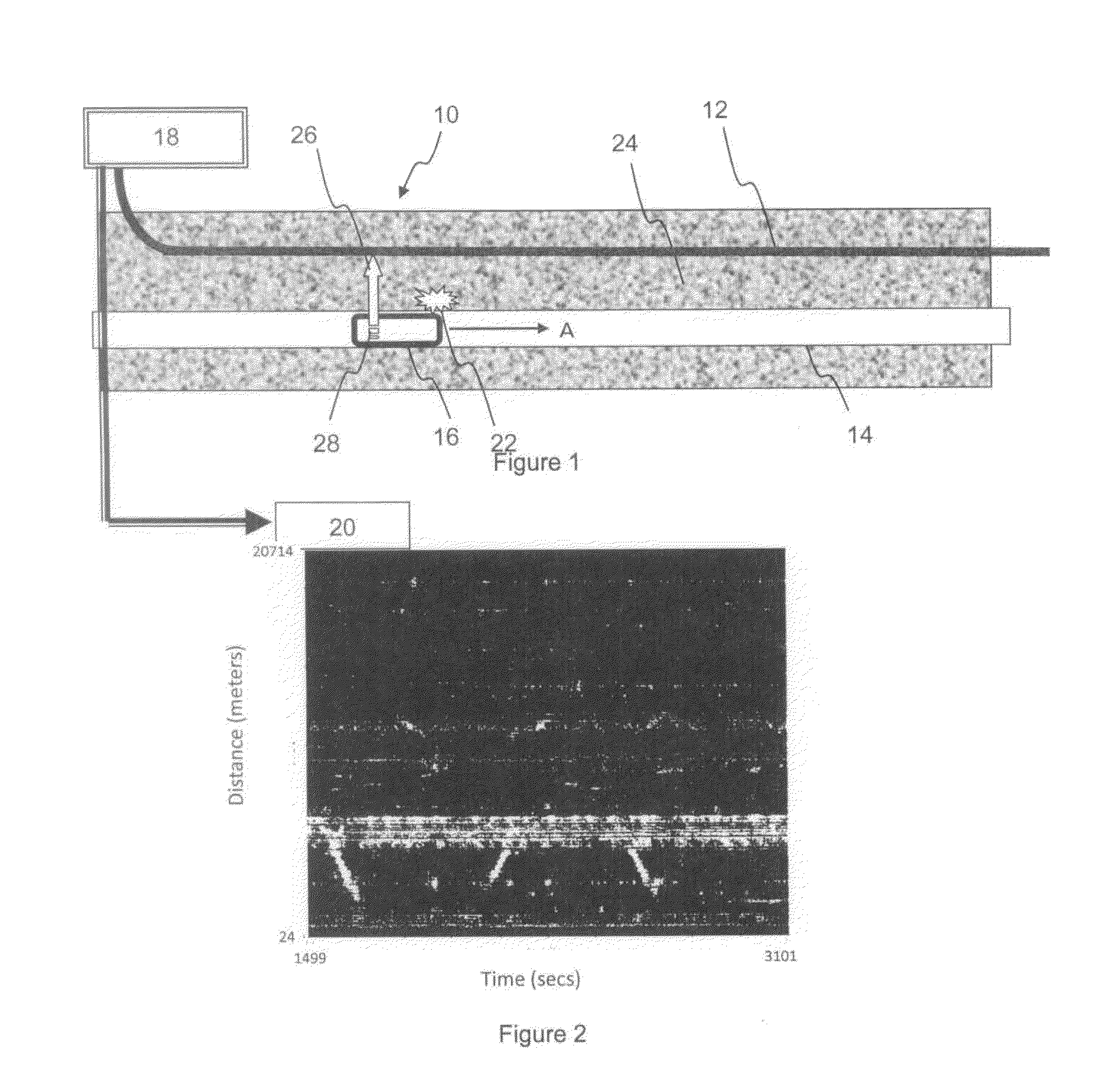
[0037]An embodiment of apparatus 10 for monitoring of a pipeline inspection tool in a pipeline according to the invention is shown in FIG. 1. The pipeline to which the apparatus according to the invention may be applied is preferably for use in the oil or gas industry.

[0038]The invention covers apparatus 10 which includes acoustic sensors in the form of an array in a sensing cable 12 that is placed on or nearby a pipeline 14 or the use of an existing system of acoustic sensors in a sensing cable 12 on or nearby a pipeline 14. The apparatus 10 of the invention further includes a pipeline inspection tool or pig 16, as it is otherwise known, and the interrogation or acquisition equipment 18 which is connected to processing equipment and software 20, the interrogation equipment 18 being connected to the acoustic sensors of sensing cable 12. The processing equipment and software 20 is used for signal processing, data archiving, data transmission, and decision making. There is then a coop...


PUM

PropertyMeasurementUnit
lengthaaaaaaaaaa
lengthaaaaaaaaaa
speedaaaaaaaaaa

Abstract

Apparatus and a method for monitoring of a pipe inspection tool in a pipeline, the apparatus comprising at least one sensor carrier apparatus being locatable along and in close proximity to a pipeline, a plurality of acoustic sensors being locatable on the sensor carrier apparatus, a pipeline inspection tool which is moveable through the pipeline being detectable by means of the acoustic sensors, and the location of the pipeline inspection tool being able to be determined by means of the acoustic sensors.

Description

TECHNICAL FIELD[0001]This invention relates to apparatus and a method for monitoring the position of a pipe inspection tool in a pipeline. In particular, the invention relates to apparatus and a method for monitoring the position of a pipe inspection tool in a pipeline in the oil and gas industry.Background Art[0002]The technology of monitoring the condition of pipelines relies on several distinct technologies, such as, for example, pigging, overflight, visual inspection, sensor monitoring such as acoustic monitoring, measurement of potential on cathodic protection systems and many others.[0003]The deployment of distributed fibre-optic sensors on a pipeline has been proposed for the simultaneous measurement of temperature, strain and disturbance affecting the pipeline. The aim of this proposed apparatus is to identify events affecting the pipeline such as leaks, ground movement and third party intervention, as well as frost heave, scouring of the backfill and many others. In additio...

Claims


Application Information

Patent Timeline
Patent Type & Authority Applications(United States)
IPC IPC(8): G01N29/04
CPCF16L55/48G01V1/001F16L2101/30F17D5/06
Inventor HARTOG, ARTHURFORBES, KEVINSTRONG, ANDREWHAMPSON, ROGER
Owner SCHLUMBERGER TECH CORP
Why Eureka
Try Eureka