High pressure sensor

a high-pressure sensor and sensor element technology, applied in the direction of fluid pressure measurement by mechanical elements, fluid pressure measurement using elastically deformable gauges, instruments, etc., can solve the problem of complicated production of welded connections having reproducible mechanical properties, difficult mounting of sensor elements on connector pieces, etc., to achieve simple and economical production

Inactive Publication Date: 2012-03-22
ROBERT BOSCH GMBH
View PDF15 Cites 1 Cited by
  • Summary
  • Abstract
  • Description
  • Claims
  • Application Information

AI Technical Summary

Benefits of technology

[0007]The present invention provides a construction concept for high-pressure sensors that enables simple and economical production of reliable high-pressure sensors even for pressure ranges above 2200 bar.

Problems solved by technology

Mounting of the sensor element on the connector piece proves to be problematic in particular when the high-pressure sensor is to be used in a pressure range above 2200 bar.
Care must be taken in this context that neither the pressure conduit in the connector piece nor the blind opening of the sensor element becomes sealed off, contaminated, or unfavorably deformed; this complicates production of a welded connection having reproducible mechanical properties.
The field of application of such high-pressure sensors is therefore typically limited to pressure ranges below 2200 bar.
The costs associated therewith are, however, very high, so that this construction and connection technology is utilized only in very small production runs for special applications.
In this case, however, because of the component size, the circuit elements for signal acquisition cannot readily be applied onto the sensor diaphragm using semiconductor technology methods.

Method used


Image

  • High pressure sensor
  • High pressure sensor

Examples


Embodiment Construction

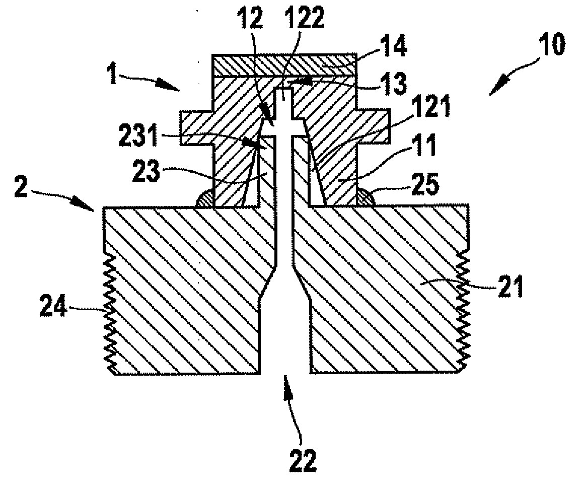
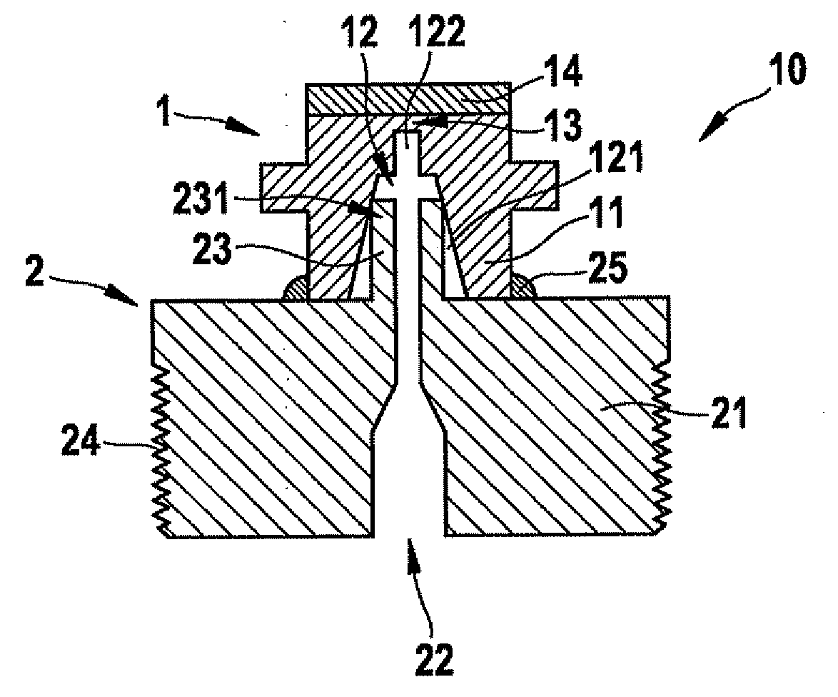
[0013]High-pressure sensor 10 depicted in the FIGURE encompasses a sensor element 1 for pressure sensing and a connector piece 2 for coupling sensor element1 to a measured system (not depicted here). Both sensor element 1 and connector piece 2 are fabricated from a respective metal base element 11, 21.

[0014]A blind opening 12 has been produced in base element 11 of sensor element 1 in order to expose a diaphragm 13 in the oppositely located surface of base element 11. This blind opening 12 has an opening region 121, tapering conically toward diaphragm 13, that transitions into a cylindrical end region 122. A functional layer 14 having circuit elements for sensing diaphragm deformations has been applied onto diaphragm 13.

[0015]A through conduit, constituting a pressure conduit 22 having a tubular prolongation 23, is embodied in base element 21 of connector piece 2. The circular cross section of pressure conduit 22 tapers, in the middle region of base element 21, down to the cross-sec...


PUM

PropertyMeasurementUnit
pressureaaaaaaaaaa
pressuresaaaaaaaaaa
pressureaaaaaaaaaa

Abstract

A construction concept for high-pressure sensors is provided, enabling simple and economical manufacture of reliable high-pressure sensors even for pressure ranges above 2200 bar. A high-pressure sensor of this kind encompasses a sensor element for pressure sensing and a connector piece for coupling the sensor element to a measured system, a diaphragm being embodied over a blind opening in the base element of the sensor element, a pressure conduit being embodied in the base element of the connector piece, and the sensor element being mounted on the connector piece in such a way that the diaphragm can be impinged upon, through the pressure conduit that opens into the blind opening, by a measured pressure. The blind opening in the base element of the sensor element is embodied, at least in one portion, in a manner tapering conically toward the diaphragm, and that end of the pressure conduit which faces toward the sensor element is tubular in shape. This tubular end of the pressure conduit is pressed into the blind opening so that the tube wall is pressed, at least in a circumferential region, sealingly against the side wall of the blind opening.

Description

FIELD OF THE INVENTION[0001]The present invention relates to a high-pressure sensor having a sensor element for pressure sensing, and having a connector piece for coupling the sensor element to a measured system. A diaphragm is embodied over a blind opening in the base element of the sensor element, and a pressure conduit is embodied in the base element of the connector piece. The sensor element is mounted on the connector piece in such a way that the diaphragm can be impinged upon, through the pressure conduit that opens into the blind opening, by a measured pressure.[0002]The sensor element and the connector piece are usually fabricated independently of one another, each from a metallic base element. In the case of the sensor element, a blind opening is generated in the base element in order to expose a diaphragm in the oppositely located surface of the base element. A functional layer having circuit elements for signal acquisition is applied onto the diaphragm surface, semiconduc...

Claims


Application Information

Patent Timeline
Patent Type & Authority Applications(United States)
IPC IPC(8): G01L7/08
CPCG01L19/0672G01L19/147
Inventor MOELKNER, THOMASFREY, WILHELM
Owner ROBERT BOSCH GMBH
Why Eureka
Try Eureka