System and method for stimulating multiple production zones in a wellbore with a tubing deployed ball seat

a technology of wellbore and production zone, which is applied in the direction of wellbore/well accessories, fluid removal, sealing/packing, etc., can solve the problems of fracture formation, high cost of renting or purchasing openhole inflatable packers (or other similar devices), and time-consuming and relatively unreliable methods

Active Publication Date: 2012-03-22
BAKER HUGHES INC
View PDF1 Cites 78 Cited by
  • Summary
  • Abstract
  • Description
  • Claims
  • Application Information

AI Technical Summary

Benefits of technology

[0019]One embodiment of the present disclosure is a method of selectively fracturing and / or treating multiple zones within a wellbore with a single trip into the wellbore with a fracture string. The method comprises running at least a first ball seat assembly into the wellbore and selectively connecting the first ball seat assembly onto a first housing on the fracture string within the wellbore. The first ball seat assembly is run into the wellbore after the fracture string has already been positioned into the wellbore. The method includes running at least a second ball seat assembly into the wellbore after running in the first ball seat assembly and selectively connecting the second ball seat assembly to a second housing on the fracture string. The method further comprises applying pressure to the fracturing string to open a hydro port sub on the fracture string and inserting a first ball into the fracture string. The first ball is adapted to seat on the first ball seat and prevent fluid flow within the fracture string past the first ball seat. The method comprises pumping fluid down the fracture string to create a pressure differential that moves a sleeve within the first housing opening a first fracture port and fracturing and / or treating the wellbore formation adjacent the first fracture port. The method comprises inserting a second ball in the fracture string that is adapted to seat on the second ball seat and prevent fluid flow within the fracture string past the second ball seat. The method includes pumping fluid down the fracture string to create a pressure differential to move a sleeve within the second housing opening a second fracture port and fracturing and / or treating the formation adjacent to the second fracture port.
[0020]The method may further comprise running a third ball seat assembly into the wellbore and selectively connecting the third ball seat assembly onto a third housing on the fracture string within the wellbore. The third ball seat assembly may be run into the wellbore after the fracturing and / or treating of the formation adjacent to the second fracture port. The method may further comprise inserting a third ball into the fracture string. The third ball being adapted to seat on the third ball seat and prevent fluid flow within the fracture string past the third ball seat. The third ball may have the same diameter as the first ball inserted into the fracture string. The method may include pumping fluid down the fracture string, after insertion of the third ball, to create a pressure differential to move a sleeve within the third housing to open a third fracture port and fracturing and / or treating the formation adjacent to the third fracture port.

Problems solved by technology

The acid may then break down the cement adjacent to the second module outside of the fracturing string and hydraulic pressure may fracture the formation at this location.
However, because of the tripping time and the difficulty in setting and maintaining the seal in inflatable packers in openhole wellbores, such a method was both time consuming and relatively unreliable.
Furthermore, openhole inflatable packers (or other similar devices) are expensive to rent or to purchase.
As a result of the relative unreliability and cost of using openhole inflatable packers, such assemblies prove to be uneconomical in marginal fields such as fields in the Permian Basin region of West Texas and Eastern New Mexico.

Method used


Image

  • System and method for stimulating multiple production zones in a wellbore with a tubing deployed ball seat
  • System and method for stimulating multiple production zones in a wellbore with a tubing deployed ball seat
  • System and method for stimulating multiple production zones in a wellbore with a tubing deployed ball seat

Examples


Embodiment Construction

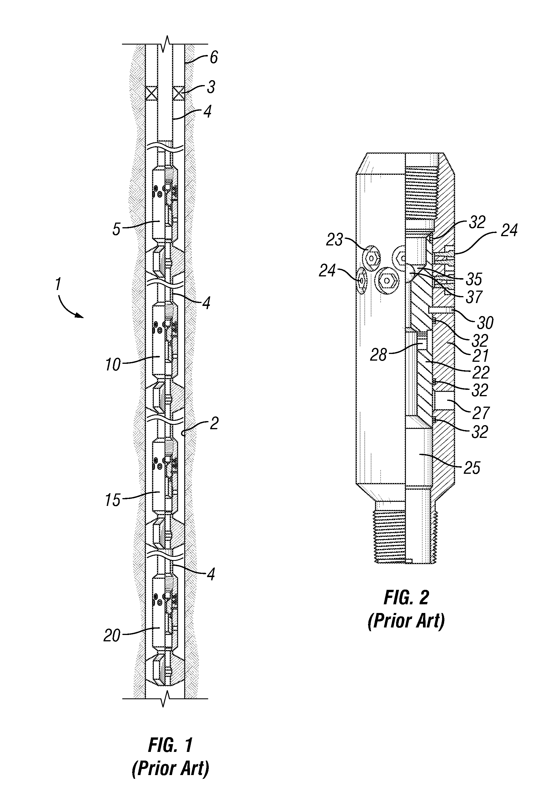
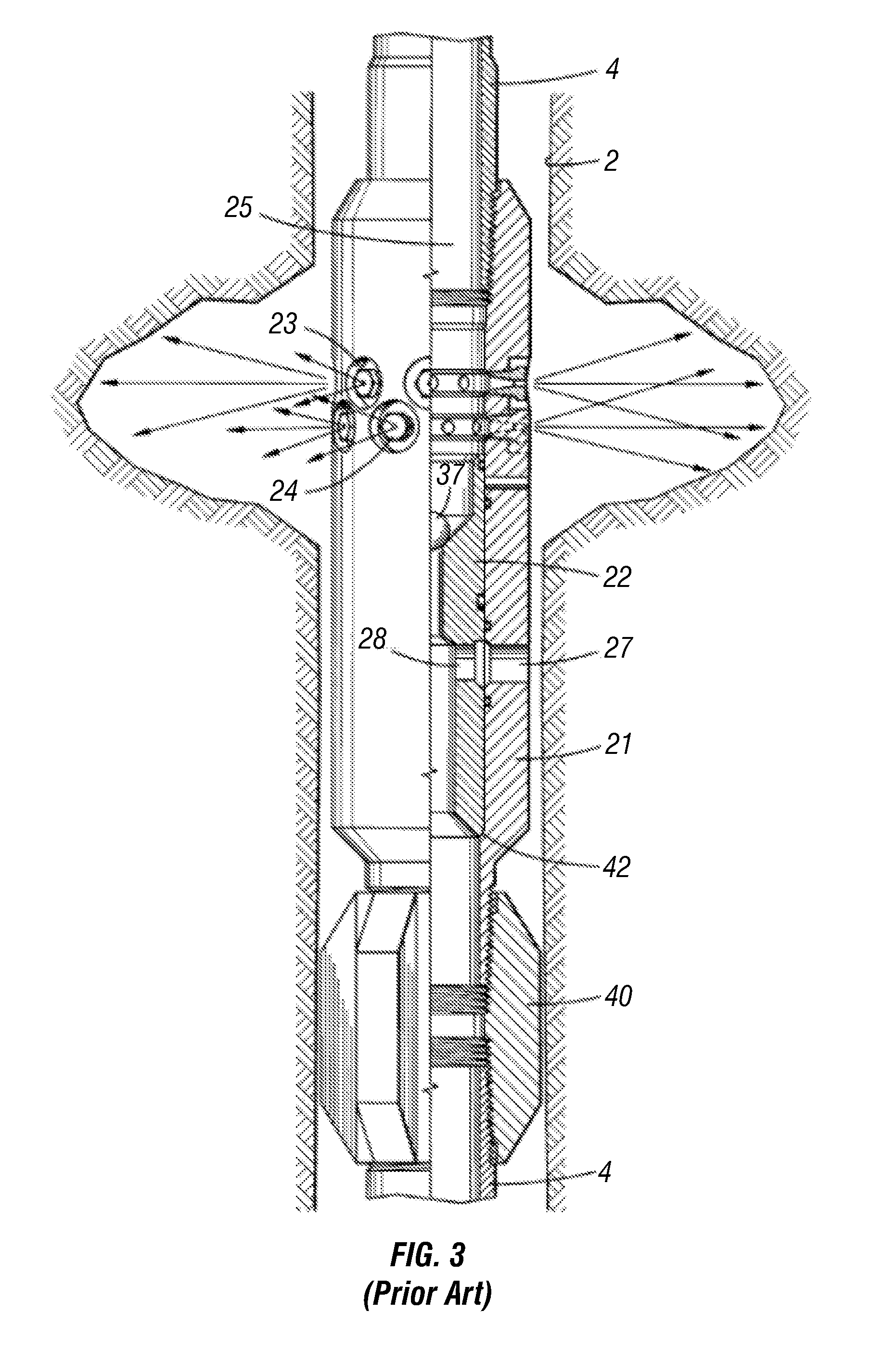
[0039]FIGS. 1-6 illustrate the fracturing string and assembly disclosed in U.S. Pat. No. 6,006,838 and U.S. Pat. No. 7,681,645, which is discussed herein to detail the process of fracturing multiple production zones within a wellbore. The present disclosure is an improved device and method for fracturing multiple production zones within a wellbore.

[0040]Referring to FIGS. 1-3, an embodiment of an assembly for selectively stimulating producing zones in a subterranean wellbore will now be described. The assembly 1 includes a plurality of modules or stages which are attached to a tailpipe 4 (shown in cutaway to reflect the longitudinal distance between the modules). The assembly in FIG. 1 includes modules 5, 10, 15 and 20. Tailpipe 4 is suspended from service packer 3 which is set inside casing 6, above the openhole wellbore 2. The service packer may be, for example, a compression packer, such as an SD-1 or MR1220 packer available from BJ Services Company. A work string of tubing, dril...


PUM


Abstract

A system and method for selectively stimulating a plurality of producing zones in a wellbore in oil and gas wells. The system includes a plurality of modules connected in a string that may be selectively actuated to stimulate a producing zone. Each module may be adapted to engage a tubing run ball seat. After installation of the string within the wellbore, a ball seat may be run into the well and positioned to selectively engage a desired module. The ball seat may be used to open a sleeve of the module permitting the stimulation of the producing zone. After stimulation of the producing zone, the ball seat may be removed from the wellbore rather than needing to drill out the ball seat. The sleeve may include a profile adapted to engage a shifting tool permitting the selective closure of the sleeve after stimulation of the producing zone.

Description

BACKGROUND[0001]1. Field of the Disclosure[0002]The present disclosure relates generally to a downhole tool for use in oil and gas wells, and more specifically, to a tubing deployed ball seat and the method for fracturing a well formation using the tubing deployed ball seat.[0003]2. Description of the Related Art[0004]If a hydrocarbon well is not adequately producing, it may be necessary to perform a completion process on the formation to stimulate a production zone, such as hydraulic fracturing the production zone. Hydraulic fracturing is typically employed to create additional passageways or otherwise increase the permeability of underground rock formations to facilitate flow through the formation to a producing well. Typically, fracturing may be accomplished by injecting a fluid containing sand or other proppant under sufficient pressure to create fractures in the rock. Fracturing the formation may be used to accomplish by a number of different methods. Methods that permit the fr...

Claims


Application Information

Patent Timeline
Patent Type & Authority Applications(United States)
IPC IPC(8): E21B43/26E21B34/06
CPCE21B34/14E21B43/26E21B43/14E21B34/142
Inventor ZIMMERMAN, MARKCOX, BLAKEHUGHES, JOHN
Owner BAKER HUGHES INC
Why Eureka
Try Eureka