
Multi-Operational Multi-Drilling System

a multi-operational, drilling system technology, applied in the direction of drilling casings, drilling pipes, underwater drilling, etc., can solve the problems of increased costs and logistical challenges, large manpower requirements of offshore drilling rig operations, and increased costs of operating these rigs

Active Publication Date: 2012-03-22
MAGNUSON PATENTS
View PDF38 Cites 51 Cited by
  • Summary
  • Abstract
  • Description
  • Claims
  • Application Information

AI Technical Summary

Problems solved by technology

Offshore rig operations require a vast amount of manpower and the cost of operating these rigs is substantial.
When drilling operations are conducted in deep water, greater costs and logistical challenges can be confronted relative to operations in shallower waters.
A major cost associated with drilling and producing a well is the cost of leasing the platform and associated equipment.
Each day of rig time can cost hundreds of thousands of dollars.
The increased costs are compounded, for example, by the additional time required to deal with the challenges of operating in deep waters, and the make-up and break-out of tubulars during a drilling operation.
Since the standard wellbay design is established in a matrix or grid format (e.g., a 4×4 layout), access to the wellbays below the rig floor is restricted by such designs.
Therefore, due to the limited access to the wellbays, such a matrix format typically allows for only a single rig function (e.g., an active drilling derrick / mast, a workover operation, a wireline operation, a coiled tubing operation, etc.) to take place at a time.
The racking of tubulars in the derrick or mast of the rig may undesirably act as a sail, imparting excessive wind loading forces onto the rig during inclement weather.
In gusting wind conditions, for example, so-designed prior art rigs can thus be adversely affected by the resulting dangerous motions and dynamics caused by the impact of the wind on the setback within the derrick or mast.
The current industry standard of locating the setback and the derrick or mast within / on the rig floor requires a high level of complexity and automation, and undesirably provides that numerous activities take place overhead of the drilling crew.
A serious cause of injury to, or even fatality of, offshore drilling rig workers is the falling of objects dropped from above the rig floor.
Such a system enhances the speed at which wellbore tasks can be completed, but does not enable multiple wellbays to be serviced simultaneously and limits operations to two activities.
Beynet et al. do not address the issues created by positioning a setback on the drilling floor in a drilling rig with regards to safety, wind loading and dynamics associated with the high CG (center of gravity) of the setback.

Method used


Image

  • Multi-Operational Multi-Drilling System
  • Multi-Operational Multi-Drilling System
  • Multi-Operational Multi-Drilling System

Examples


Embodiment Construction

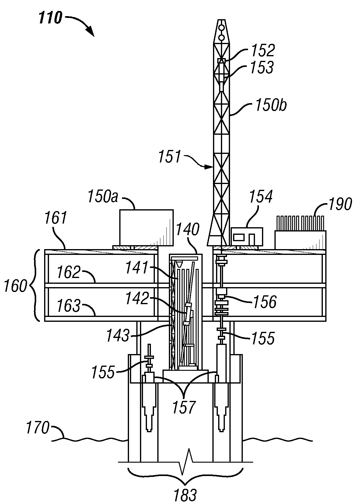
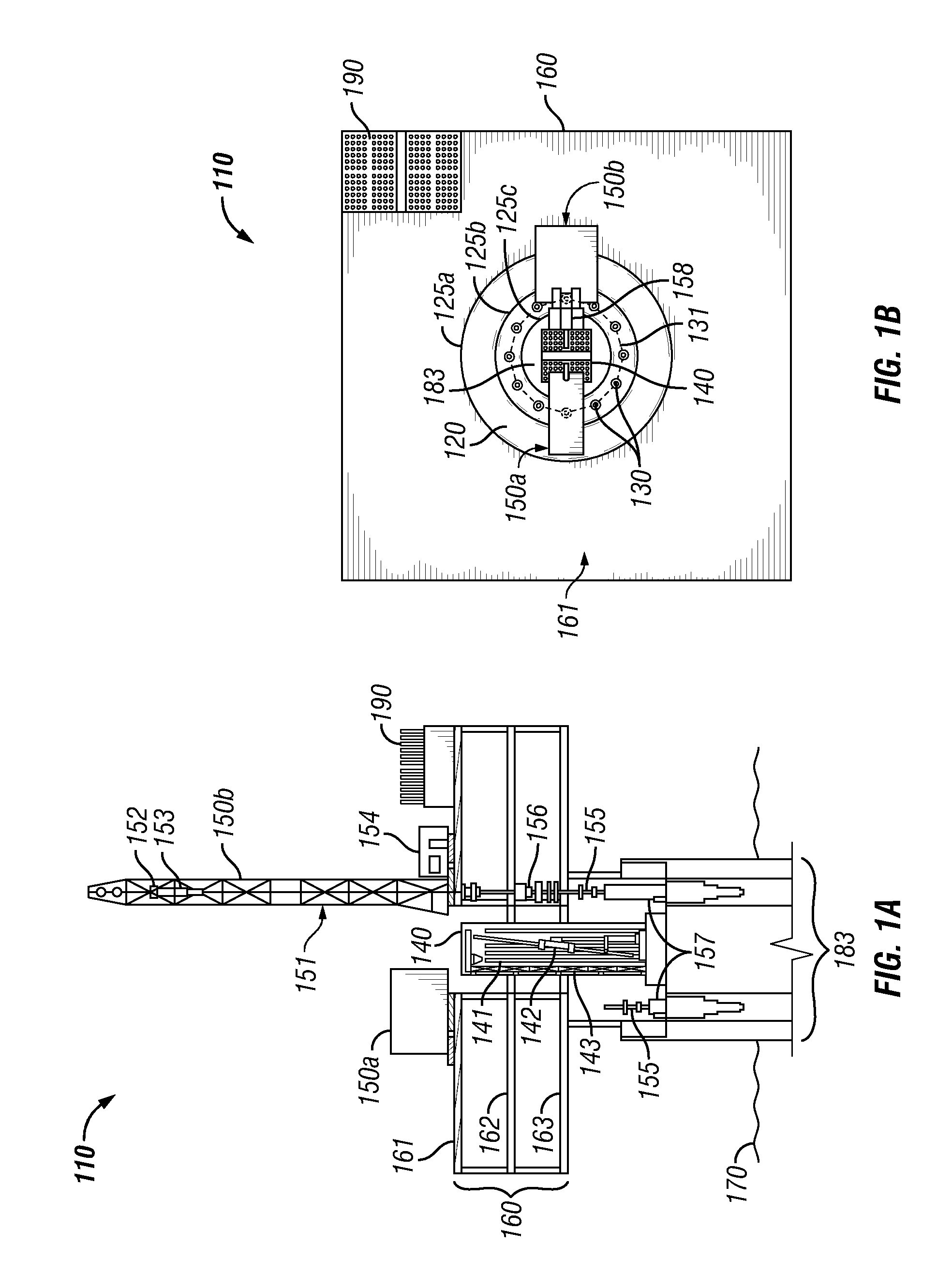
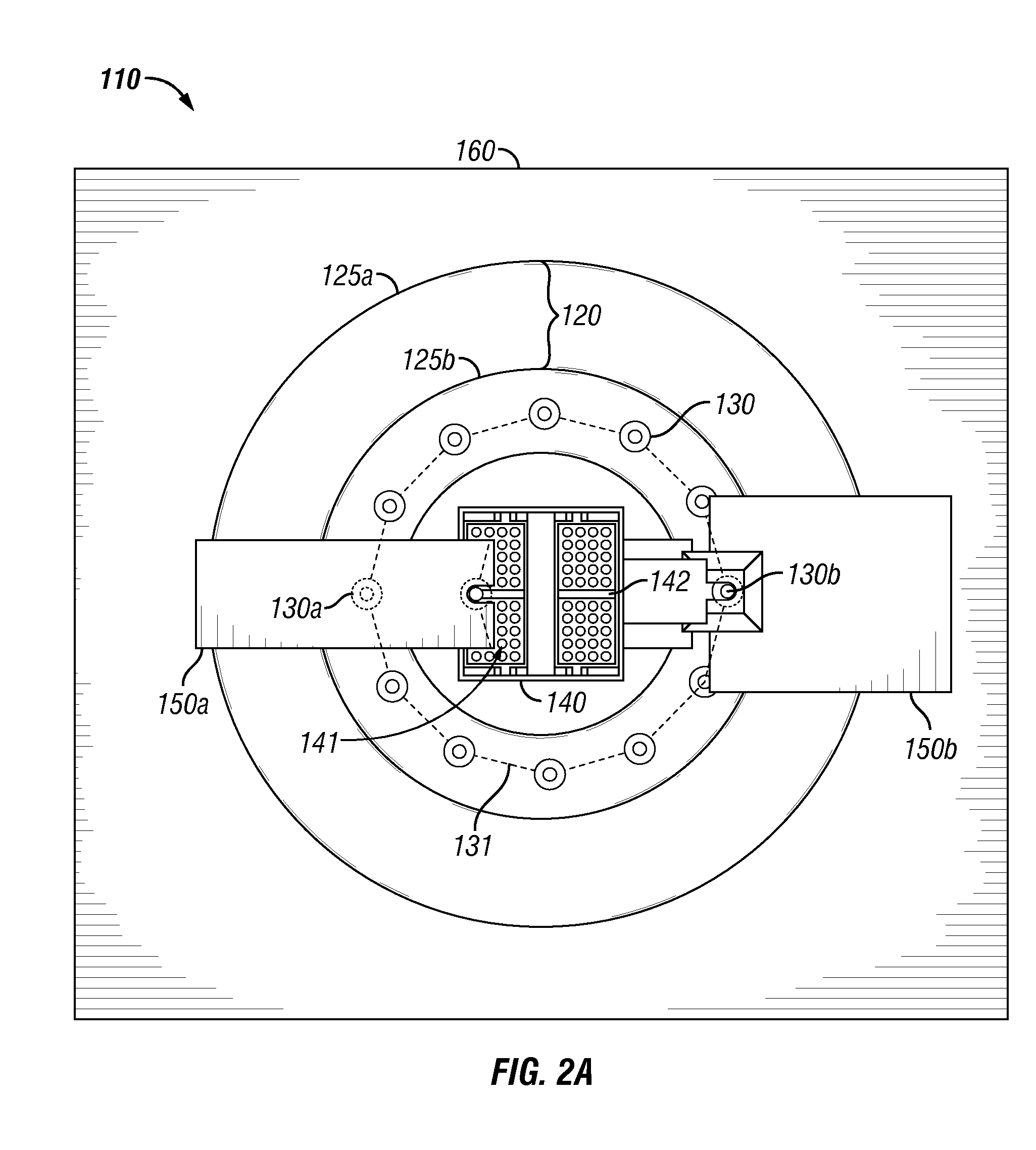
[0052]Overview. Herein disclosed is a multi-operational drilling system (hereinafter, ‘MODS’) or multi-operational wellbore forming system for performing multiple operations associated with drilling. Also disclosed herein is a method of drilling and / or servicing a plurality of wellbores (for example wellbores in the seafloor), utilizing the disclosed multi-operational drilling system. The herein disclosed multi-operational peripheral drilling system and method enable the advancement of oil, gas and water wellbore drilling, completion, wireline, coil tubing, and / or workover operations, by allowing multiple operations associated with drilling to be completed simultaneously, with greater safety than conventional drilling systems that employ drilling rigs comprising elevated rig floor and setback and racking systems and / or centralized drilling (as opposed to the herein disclosed peripheral drilling).

[0053]In embodiments, an MODS of this disclosure comprises a substantially centralized s...


PUM


Abstract

A system including a setback and racking system and a set of wellbay accesses, at least a portion of the setback and racking system positioned at an elevation lower than the elevation of the wellbay accesses. A system including a centrally located setback and racking system, a set of wellbay accesses, and at least one peripheral skidding system, wherein the setback and racking system is positioned at least partially below the elevation of the peripheral skidding system. A system including at least one peripheral skidding system and a set of wellbay accesses positioned along a wellbay access perimeter surrounding a central focus that is not an integral part of the peripheral skidding system. A method of drilling by aligning each of at least two drilling modules with a respective wellbay access via a peripheral skidding system and operating at least two drilling modules at least partially simultaneously.

Description

CROSS-REFERENCE TO RELATED APPLICATIONS[0001]This application claims the benefit under 35 U.S.C. §119(e) of U.S. Provisional Patent Application No. 61 / 454,867, filed Mar. 21, 2011, and U.S. Provisional Patent Application No. 61 / 403,248, filed Sep. 13, 2010, the disclosures of each of which are hereby incorporated herein by reference.STATEMENT REGARDING FEDERALLY SPONSORED RESEARCH OR DEVELOPMENT[0002]Not Applicable.BACKGROUND[0003]1. Field of the Invention[0004]The present disclosure relates generally to a multi-operational system for use in petroleum exploration and development. More particularly, the present disclosure relates to a drilling system comprising a peripheral skidding system and / or a removed, lowered, and centrally located setback and racking system to enable a plurality of operations, such as, but not limited to, offline stand building and racking of tubulars, workover, and drilling operations, to be performed concurrently.[0005]2. BACKGROUND OF THE INVENTION[0006]Off...

Claims


Application Information

Patent Timeline
IPC IPC(8): E21B7/128E21B19/00
CPCE21B15/003E21B7/12E21B19/002E21B19/143E21B7/128E21B15/02
Inventor MAGNUSON, CHRISTOPHER
Owner MAGNUSON PATENTS
Features
  • Generate Ideas
  • Intellectual Property
  • Life Sciences
  • Materials
  • Tech Scout
  • Unparalleled Data Quality
  • Higher Quality Content
  • 60% Fewer Hallucinations
Learn More