Overhead Storage Device

a storage device and overhead technology, applied in the field of storage devices, can solve problems such as damage to the load and/or the storage device, and achieve the effect of preventing an accidental release of the locking mechanism and taking less headroom

Inactive Publication Date: 2012-03-22
OZARSKI ROBERT
View PDF6 Cites 21 Cited by
  • Summary
  • Abstract
  • Description
  • Claims
  • Application Information

AI Technical Summary

Benefits of technology

[0005]The present invention provides an overhead storage device. The device is particularly suited for storing items commonly stored in a garage, such as bicycles, golf clubs, and yard equipment, which occupy floor space and often exclude the ability to park an automobile in the garage. In particular the device includes a mechanism for hoisting the object to be stored such as a bicycle above floor level. The device includes a cable with an attachment mechanism at one end of the cable. The cable is partially wound on a spool. A constant torque spring applies an approximately constant torque to the spool. This approximately constant torque continuously causes the cable, unless restrained, to be further wound on the spool. The device includes a special locking mechanism which allows the attachment mechanism and an attached load to be lowered and locked at any desired position within the range of the device. In preferred embodiments the locking mechanism includes a pawl and ratchet unit adapted to restrain any lifting of the load unless a release cord attached to the pawl (between a pivot axis of the pawl and the ratchet) is pulled downward. The pawl and ratchet unit is preferably designed to require a downward force greater than the typical load to be applied to the release cord in order to pull the cord downward releasing the locking mechanism (if no load (or a relatively light load) is attached to the attachment mechanism. This feature prevents an accidental release of the locking mechanism when no load is attached to the attachment mechanism. Such an accidental release could damage the load and / or the storage device.
[0006]Preferred embodiments provide for the storage of two bicycles on two independent pivoting arms, by raising each separately from a standing position on the floor to a position near or at the ceiling or in the case of an open beam and rafter between the joists for storage out of way of persons or objects. The preferred device further allows the bicycles held by the storage device to be positioned by separate pivoting arms for each bicycle in an arc about the central support shaft such that the bikes may be independently positioned at the ceiling against a wall or above other obstacles or a vehicle such as an automobile, truck or SUV for storage in their raised position through the spring and pulley system. The Pivoting arms allow the bicycles to be raised and lowered from a convenient location within an arc around the main support shaft and then pivoted to the desired storage location, which can be above other objects which would otherwise interfere with raising and lowering if the pivoting capability was not present. The main support is accomplished by “pinching the vertical support between the ceiling and the floor to support the load with no load bearing fasteners to the ceiling, floor or walls. A means are also provided to tilt the bicycle horizontally as it is raised to allow it to take less headroom when it is stored.
[0007]The lifting mechanism may also be mounted independently of the pivoting arms and support pole in a fixed position. Alternative mounting means are where the lift mechanism is mounted directly to the ceiling rafters or a wall by means of securing bolts and or mounted in a position which straddles the joists, where it is secured by screws or bolts. The invention is not limited to lifting of bicycles. The device allows for other items to be stored, such as golf clubs, yard equipment, etcetera, out of the way, by raising them above floor level.

Problems solved by technology

Such an accidental release could damage the load and / or the storage device.

Method used


Image

  • Overhead Storage Device
  • Overhead Storage Device
  • Overhead Storage Device

Examples


Embodiment Construction

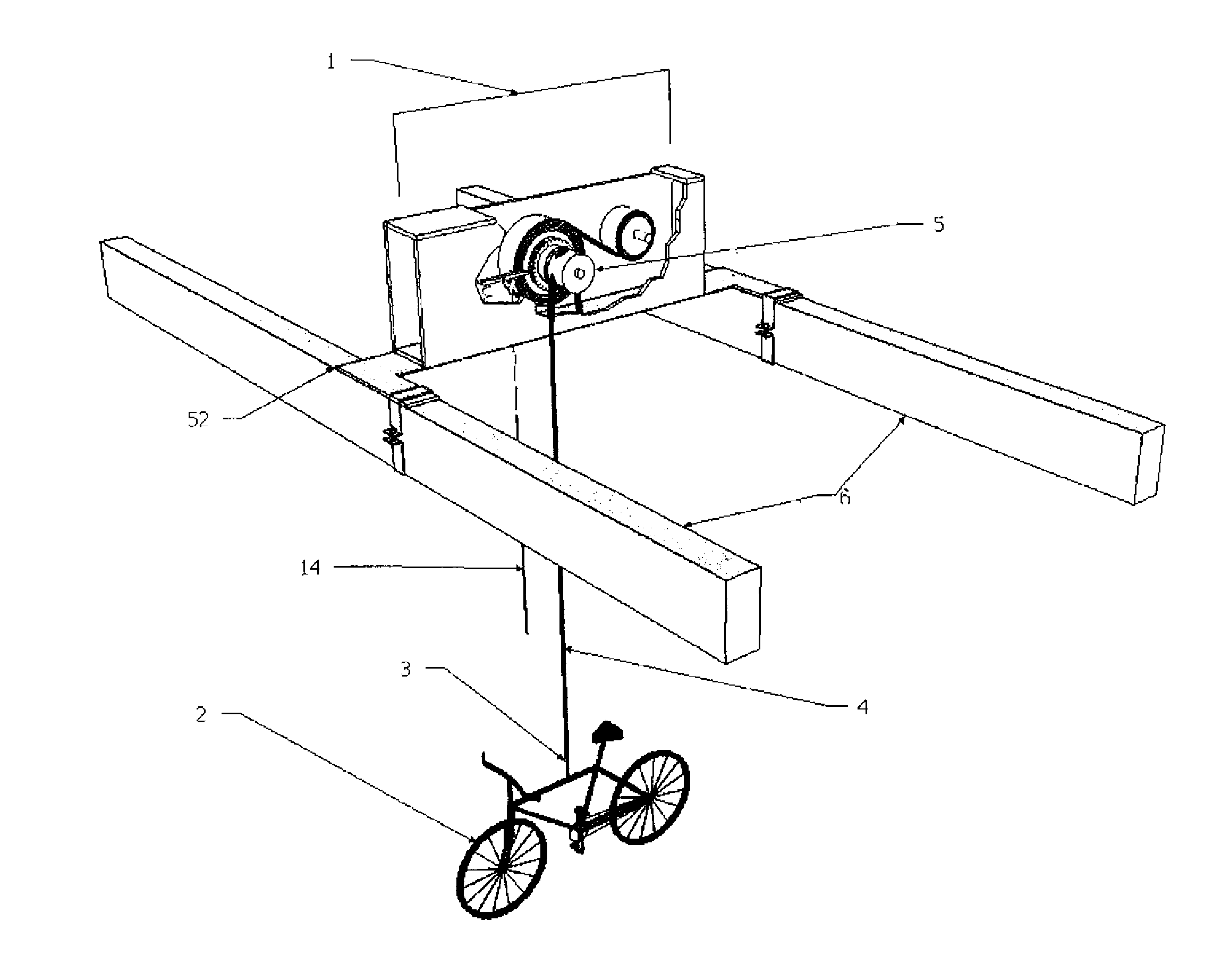
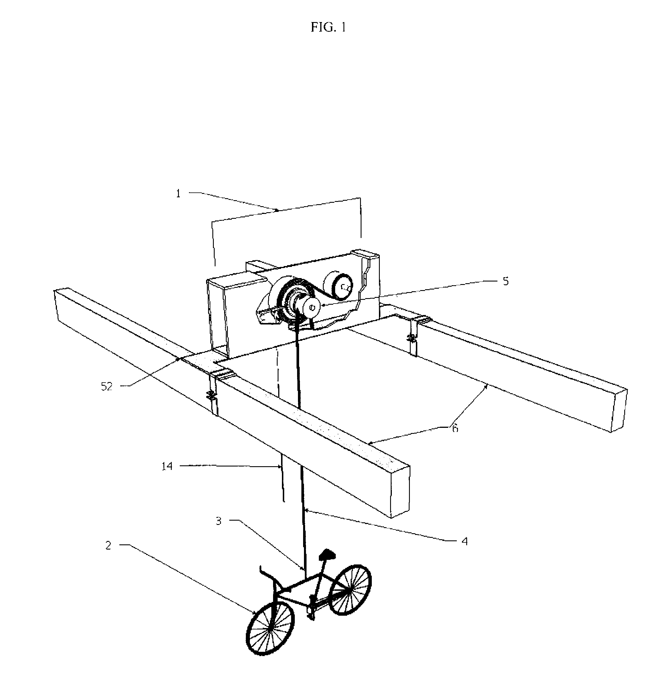
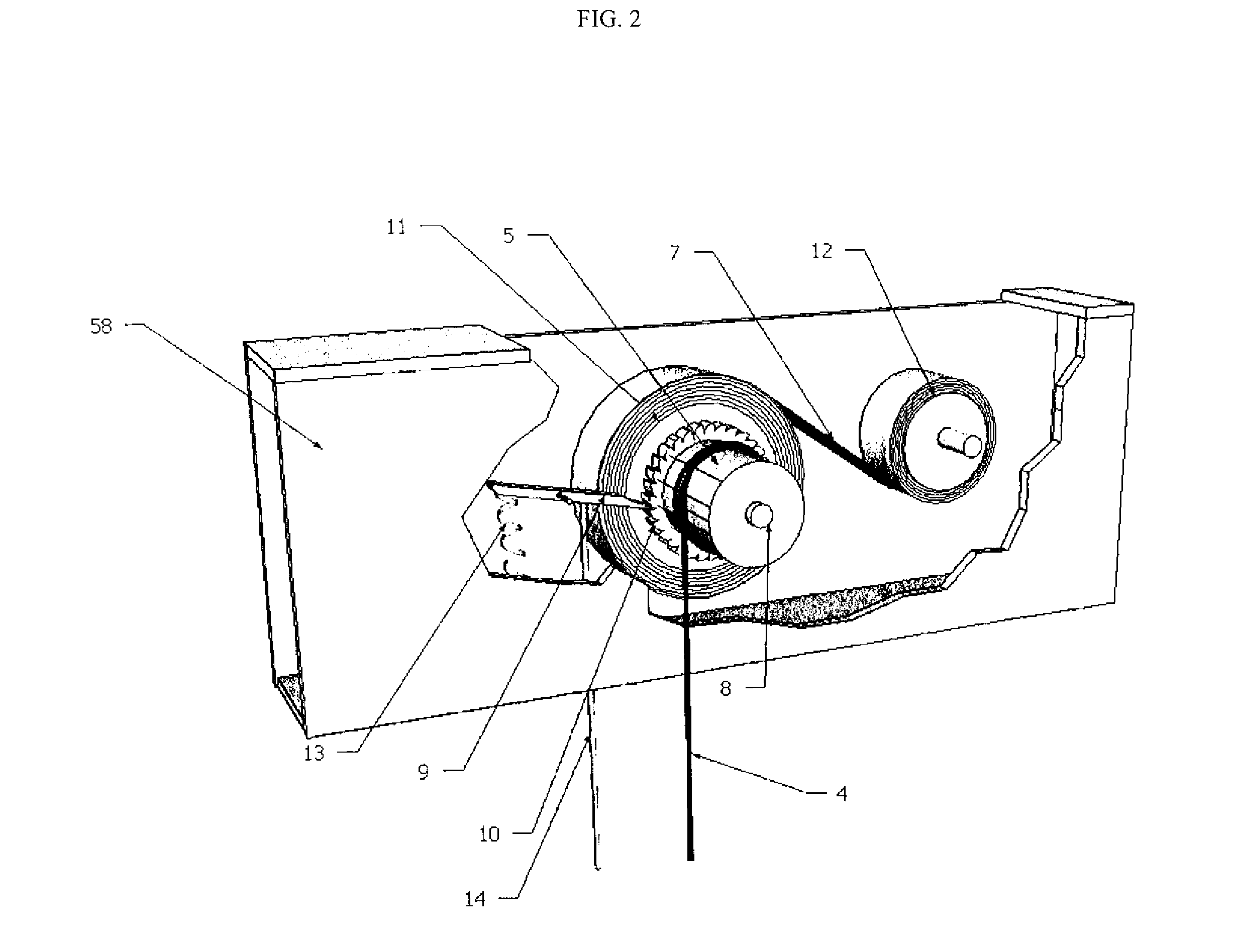
[0014]FIG. 1 shows a bicycle storage device, which allows a bicycle to be lifted by a constant torque spring mechanism 1 and pulley system 5, from its standing position on the ground to a position at the top of the lifting device's travel for storage. A bicycle 2 or other load is attached by a load hook 3, as shown in FIG. 1 to a lift cable 4 suspended by the device's power pulley 5 which is attached to containment box 58 through a shaft 8, shown in FIG. 2. A constant torque spring 7, supplies a force slightly greater than the weight of the object load (bicycle), such that the load object will rise until the maximum lift height is reached or the object reaches the ceiling. A preferred constant torque spring is available from Vulcan Springs, Inc. with offices in Telford, Pa.

[0015]The object load (bicycle) is lowered by manually applying a small amount of downward force, by pulling downward on the object attached to the load hook 3. As the object load 2 (a bicycle) of FIG. 1 is lowere...


PUM


Abstract

An overhead storage device having a lifting range. A constant torque spring is attached to a power pulley and is adapted to apply an approximately constant torque to the power pulley. A cable is partially wound around the power pulley and has an attachment mechanism at one end of the cable. A locking mechanism is adapted to permit the attachment mechanism and an attached load to be lowered and locked at any desired position within the range of the device. The approximately constant torque applied by the constant torque spring continuously causes the cable, unless restrained, to be further wound on the pulley.

Description

FIELD OF THE INVENTION[0001]This application claims the benefit of Provisional Application 61 / 403,487 filed Sep. 16, 2010, which is incorporated by reference herein. The present invention relates to storage devices and in particular to overhead storage devices.BACKGROUND OF THE INVENTION[0002]Most families in the United States own one or more bicycles. Only a small portion of the populations regularly rides the bicycles. Most bicycles in the United States are in storage, often with flat tires and rusty chains. Many bicycle storage devices have been proposed. Many of these devices seek to store the bicycles in spaces not needed for other uses, such as up above floor spaces, for example, by hanging the bicycle from a ceiling in a garage, above normal automobile spaces. Some prior art patents covering bicycle storage include the following U.S. Pat. Nos.: 3,872,972, 6,161,207, 3,907,113 and 5,183,162. U.S. Pat. No. 3,872,972 includes a rack for hanging a bicycle above the floor and incl...

Claims


Application Information

Patent Timeline
Patent Type & Authority Applications(United States)
IPC IPC(8): B66D1/14B66D5/34
CPCB66D1/02B62H3/12
Inventor OZARSKI, ROBERT
Owner OZARSKI ROBERT
Why Eureka
Try Eureka