

Guiding device and projector comprising the same
- Summary
- Abstract
- Description
- Claims
- Application Information
AI Technical Summary
Benefits of technology
Problems solved by technology
Method used
Image

Examples
first embodiment
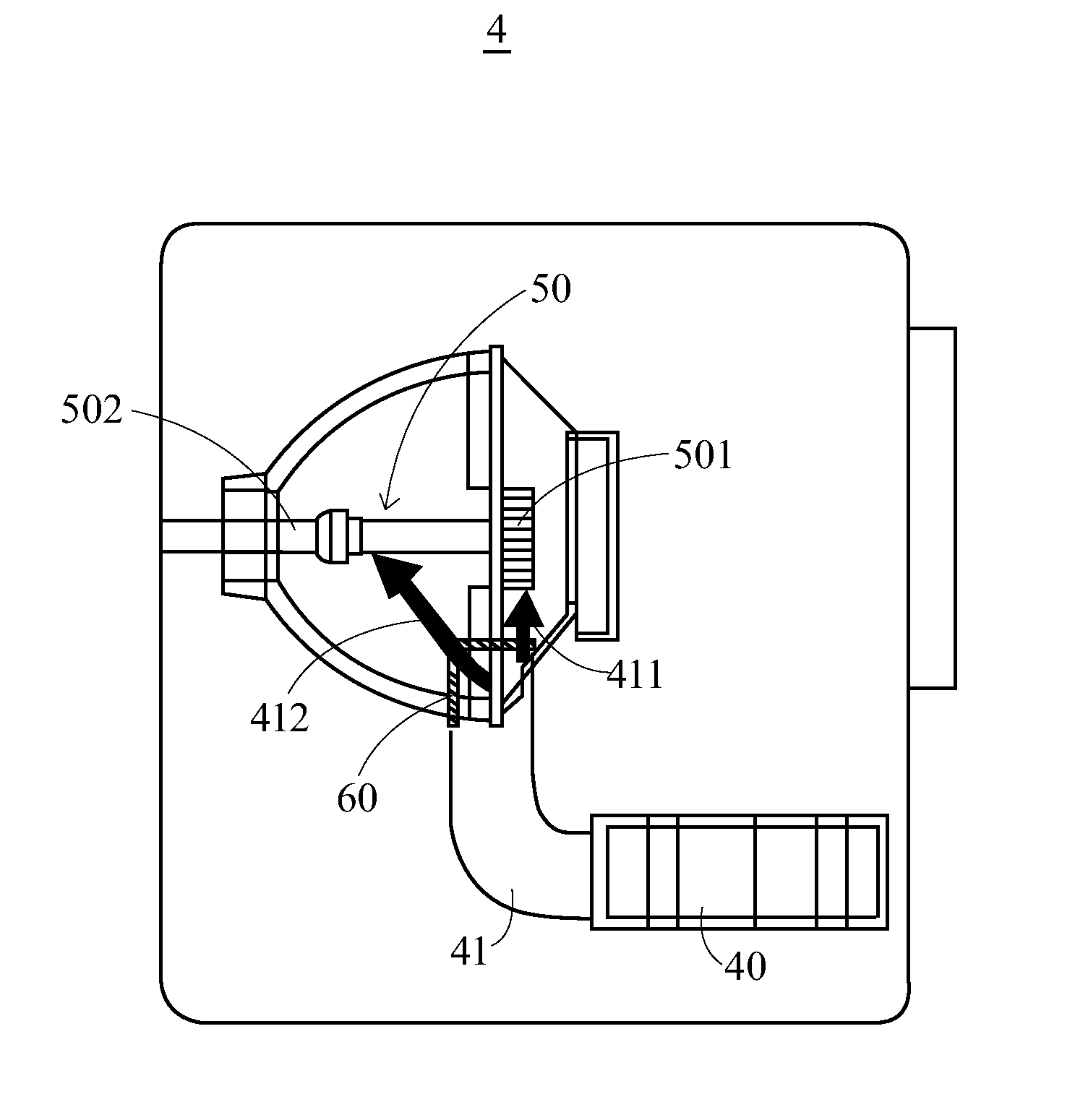
[0027]the guiding device 60 of the present invention is shown in FIG. 3A. The body 61 of the guiding device 60 has a slot 613 disposed in the second outlet 612, and two lateral edges of the flapper 62 are slidably disposed in the slot 613. When the projector 4 is in an upright orientation, the flapper 62 moves along the direction of gravity in the slot 613 to partially cover the lower portion of the second outlet 612 and guide the second airflow 412 towards the upper portion 502a of the rear end 502 of the bulb 50 away from the direction of gravity. On the other hand, when the projector 4 is placed upside down (e.g., hung upside down from a ceiling), the flapper 62 slides downwards along the slot 613 with gravity from the original position in the upright status of the projector 4 to partially cover the lower portion of the second outlet 612 again; as a result, the second airflow 412 still flows toward the upper portion 502a of the rear end 502 of the bulb 50 to lower the temperature...
second embodiment
[0028]the present invention is shown in FIG. 3B. The body 61 of the guiding device 60 has a slot 616 of another form, which is disposed adjacent to the second outlet 612. Correspondingly, the guiding device 60 comprises a flapper 64 of another form, which has at least one protruding portion 641 slidably disposed in the slot 616. In this embodiment, the number of the at least one protruding portion 641 may be two. Through the sliding of the protruding portions 641 in the slot 616, the flapper 64 slides towards the lower portion of the second outlet 612 with gravity to partially cover the lower portion of the second outlet 612 and guide the second airflow 412 towards the upper portion 502a of the rear end 502 of the bulb 50.
[0029]As shown in FIG. 3C, the third embodiment of the present invention is similar to the second embodiment. The flapper 64 of the third embodiment may further comprise a sliding portion 642 and a guiding portion 643. The protruding portions 641 are formed on the ...
fourth embodiment
[0030]the present invention is shown in FIG. 3D. The body 61 of the guiding device 60 has a pivot 614 disposed in the second outlet 612, and in this embodiment, a lateral edge 661 of the flapper 66 is joined to the pivot 614 to swing up and down around the pivot 614. Therefore, with gravity, the flapper 66 swings towards the lower portion of the second outlet 612 to partially cover the second outlet 612 and guide the second airflow 412 towards the upper portion 502a of the rear end 502 of the bulb 50. In this embodiment, the body 61 may further comprise two bumps 615 disposed adjacent to an upper end 612a and a lower end 612b of the second outlet 612 respectively to stop the flapper 66 when the flapper 66 swings to the upper end 612a or the lower end 612b by swinging with an angle no greater than 180 degrees. Thereby, the swaying of the flapper 66 due to the airflow, which would otherwise make it impossible to effectively cover the lower portion of the second outlet 612, can be avoi...
PUM
 Abstract
Description
Claims
Application Information