Over-The-Air Test

a test and over-the-air technology, applied in the field of over-the-air testing, can solve the problems of increasing the complexity of the testing system, affecting the operation of the radio connection, and different strengths of the received signal fading,

Active Publication Date: 2012-03-22
KEYSIGHT TECH SINGAPORE (SALES) PTE LTD
View PDF11 Cites 51 Cited by
  • Summary
  • Abstract
  • Description
  • Claims
  • Application Information

AI Technical Summary

Benefits of technology

[0013]The invention provides several advantages. The DUT may be tested from different directions without problems with cables or complexity by shifting the simulated radio channel electronically with respect to the DUT.

Problems solved by technology

When a radio frequency signal is transmitted from a transmitter to a receiver, the signal propagates in a radio channel along one or more paths having different angles of arrivals, signal delays, polarizations and powers, which cause fadings of different durations and strengths in the received signal.
In addition, noise and interference due to other transmitters interfere with the radio connection.
However, rotation causes problems in cabling since cables between the subscriber terminal and the emulator cannot rotate too much.
Additionally, the complexity of the testing system increases by the application of a rotation mechanism, such as a motor and a turning table driven by the motor, and its control.

Method used


Image

  • Over-The-Air Test
  • Over-The-Air Test
  • Over-The-Air Test

Examples


Embodiment Construction

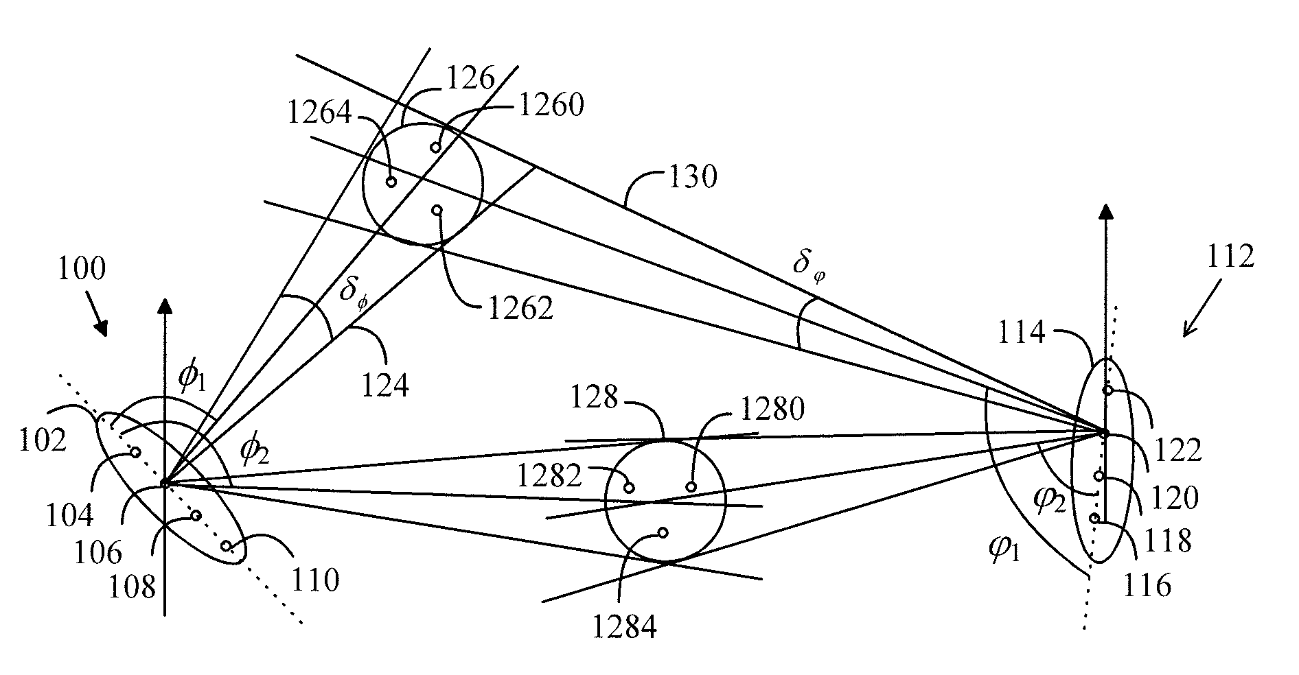
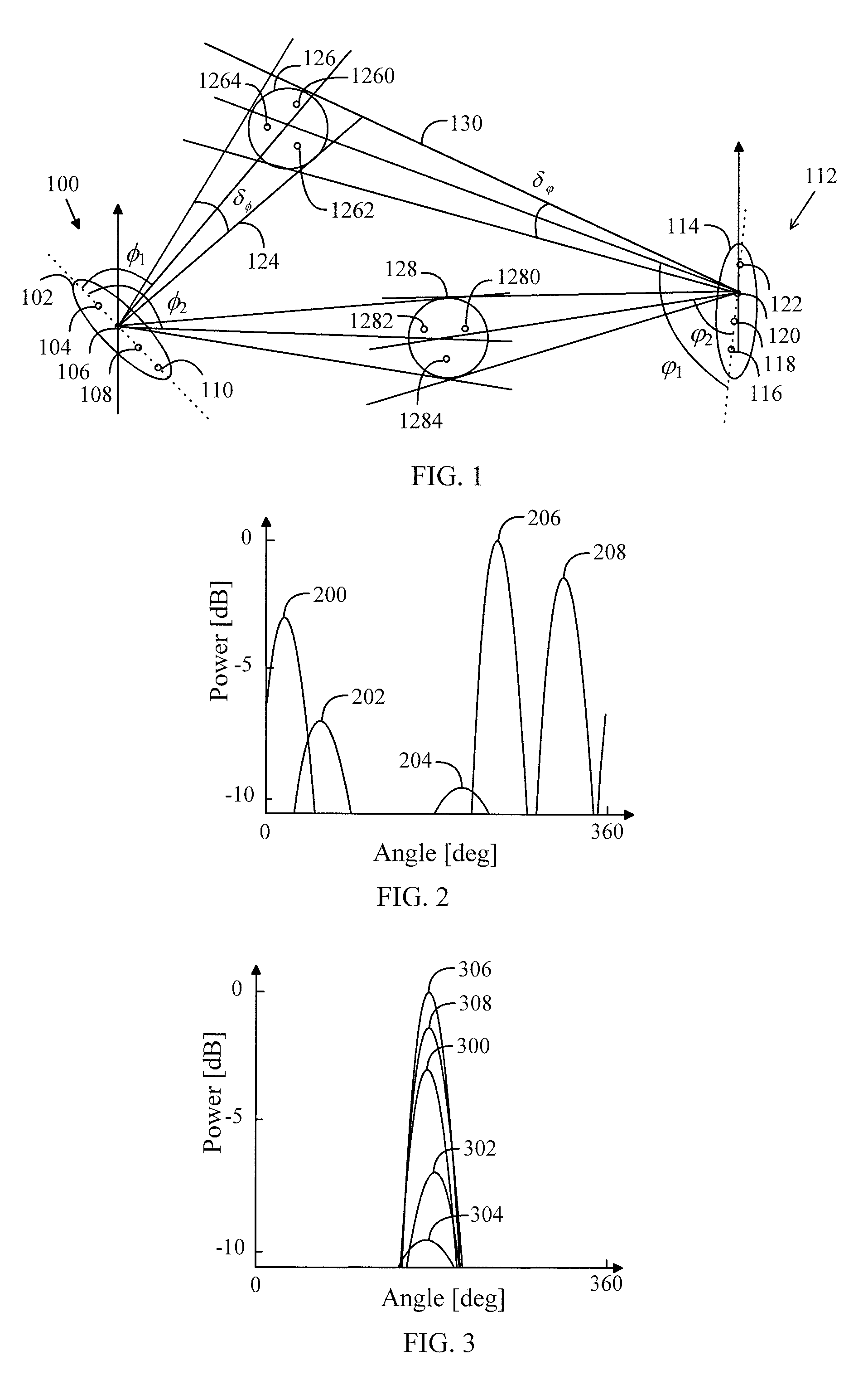
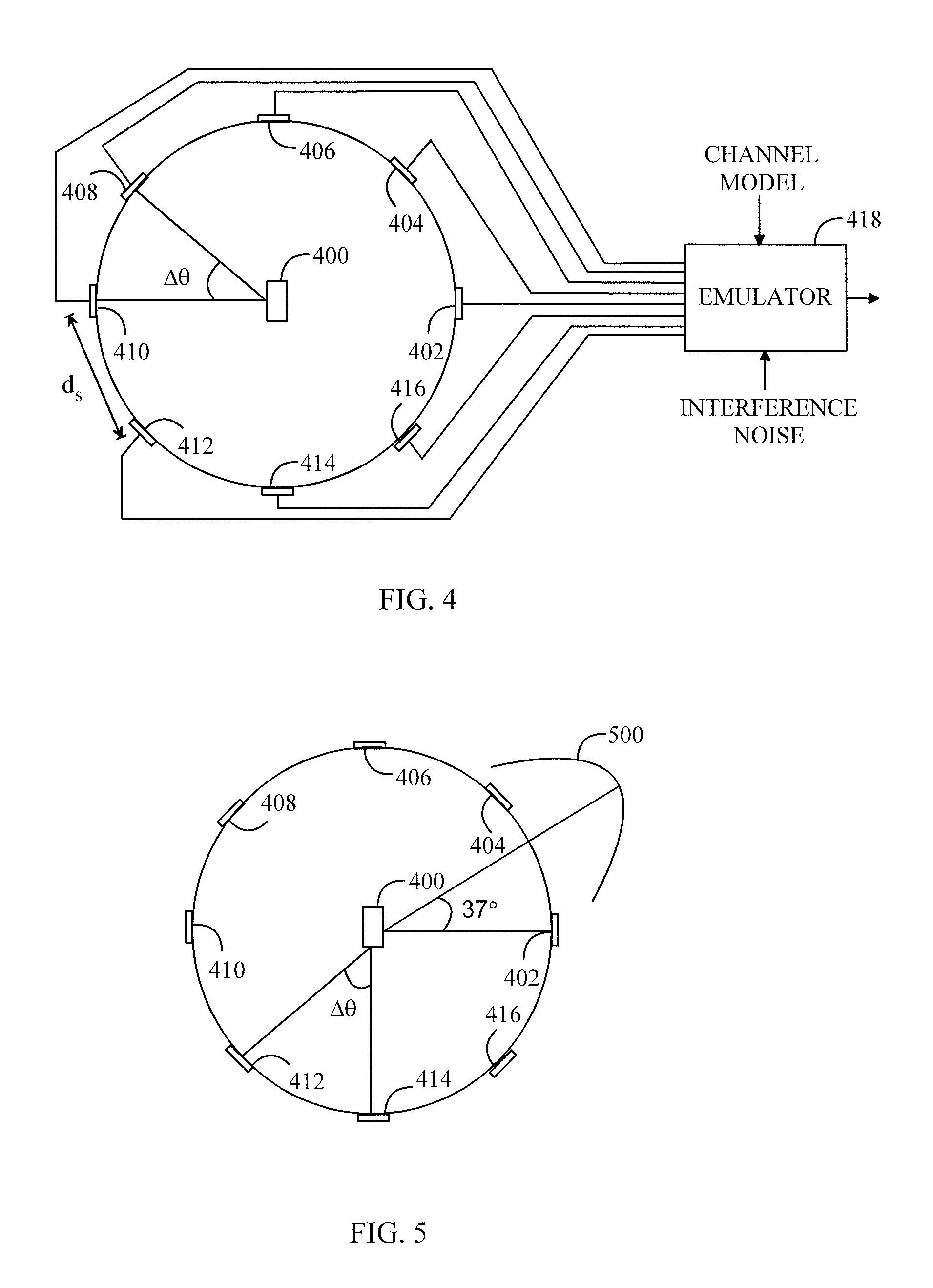
[0045]Channel impulse responses and optimization of the antenna weights in OTA may be formed so that an accurate correlation, an angle of arrival and polarization properties are possible for a DUT. The described solution may use a transmitter, a multidimensional radio channel emulator, an anechoic chamber, antenna elements coupled with separate radio channels inside the anechoic chamber and a DUT in the anechoic chamber, for example. The simulated radio channel may be shifted with respect to the angle of arrival on the DUT such that the same power angular spectrum can be used in communication at different angles at different moments of time.

[0046]FIG. 1 illustrates propagation of a radio signal between a transmitter and a receiver. The transmitter 100 may comprise an antenna 102 of at least one antenna element 104 to 110. The antenna may be, for example, ULA (Uniform Linear Array) antenna where the spacing between the antenna elements is constant, for example half the wavelength of ...


PUM


Abstract

A simulated radio channel is shifted with respect to a plurality of antenna elements coupled with an emulator for communicating with a device under test by using different directions for the simulated radio channel in an anechoic chamber.

Description

CROSS-REFERENCE TO RELATED APPLICATION[0001]This application is a National Stage application of International Application No. PCT / FI2009 / 050471, filed Jun. 3, 2009, which is incorporated by reference herein in its entirety.BACKGROUND[0002]1. Field[0003]The invention relates to an over-the-air testing of a device in an anechoic chamber.[0004]2. Description of the Related Art[0005]When a radio frequency signal is transmitted from a transmitter to a receiver, the signal propagates in a radio channel along one or more paths having different angles of arrivals, signal delays, polarizations and powers, which cause fadings of different durations and strengths in the received signal. In addition, noise and interference due to other transmitters interfere with the radio connection.[0006]A transmitter and a receiver can be tested using a radio channel emulator emulating real circumstances. In a digital radio channel emulator, a channel is usually modeled with an FIR filter, which generates co...

Claims


Application Information

Patent Timeline
Patent Type & Authority Applications(United States)
IPC IPC(8): H04B17/00
CPCH01Q3/24H01Q3/26H04B17/391H04B7/088H04B17/0087H04B7/0695G01R29/08H04B17/00
Inventor FALCK, MARKOKYOSTI, PEKKAHEINO, PETTERINUUTINEN, JUKKA-PEKKASAASTAMOINEN, JOUNI
Owner KEYSIGHT TECH SINGAPORE (SALES) PTE LTD
Why Eureka
Try Eureka