Hybrid bone plate

Active Publication Date: 2012-03-22
STRYKER EURO OPERATIONS HLDG LLC
View PDF11 Cites 11 Cited by
  • Summary
  • Abstract
  • Description
  • Claims
  • Application Information

AI Technical Summary

Benefits of technology

[0004]In view of the known prior art, it may be seen as an object of the present invention to provide for a hybrid bone plate allowing

Problems solved by technology

Press-fitting for example does not form a closed integral surface, because the transition between the first plate portion and the secon

Method used


Image

  • Hybrid bone plate
  • Hybrid bone plate
  • Hybrid bone plate

Examples


Example

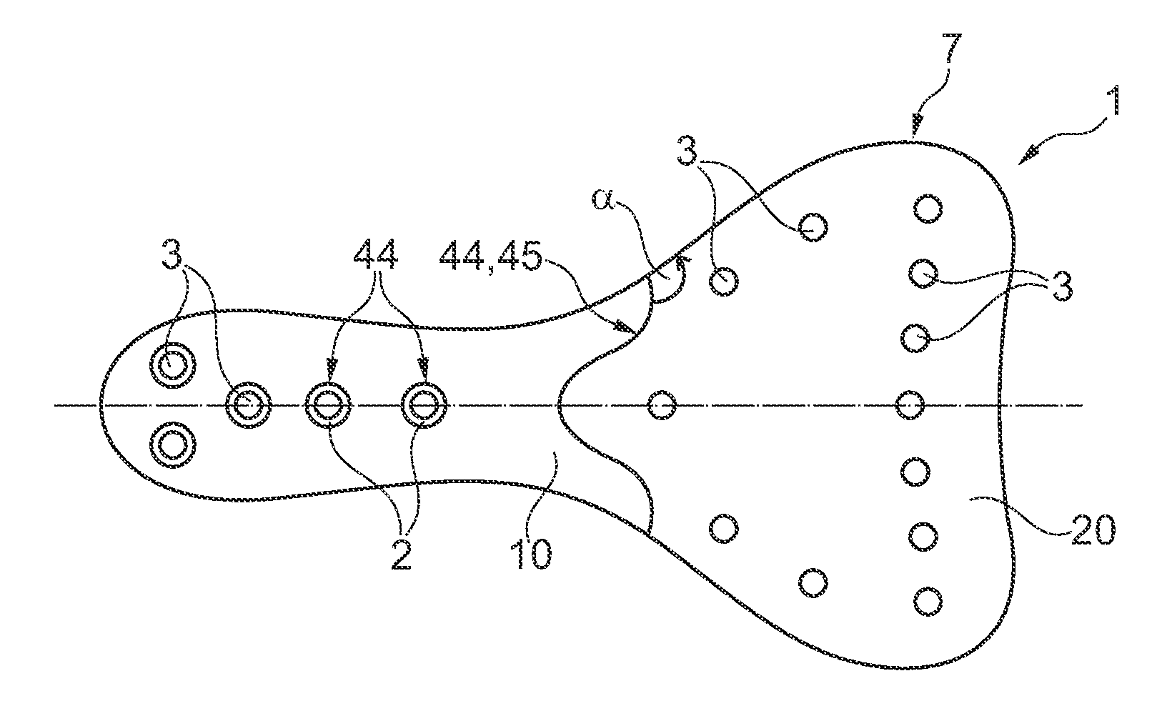
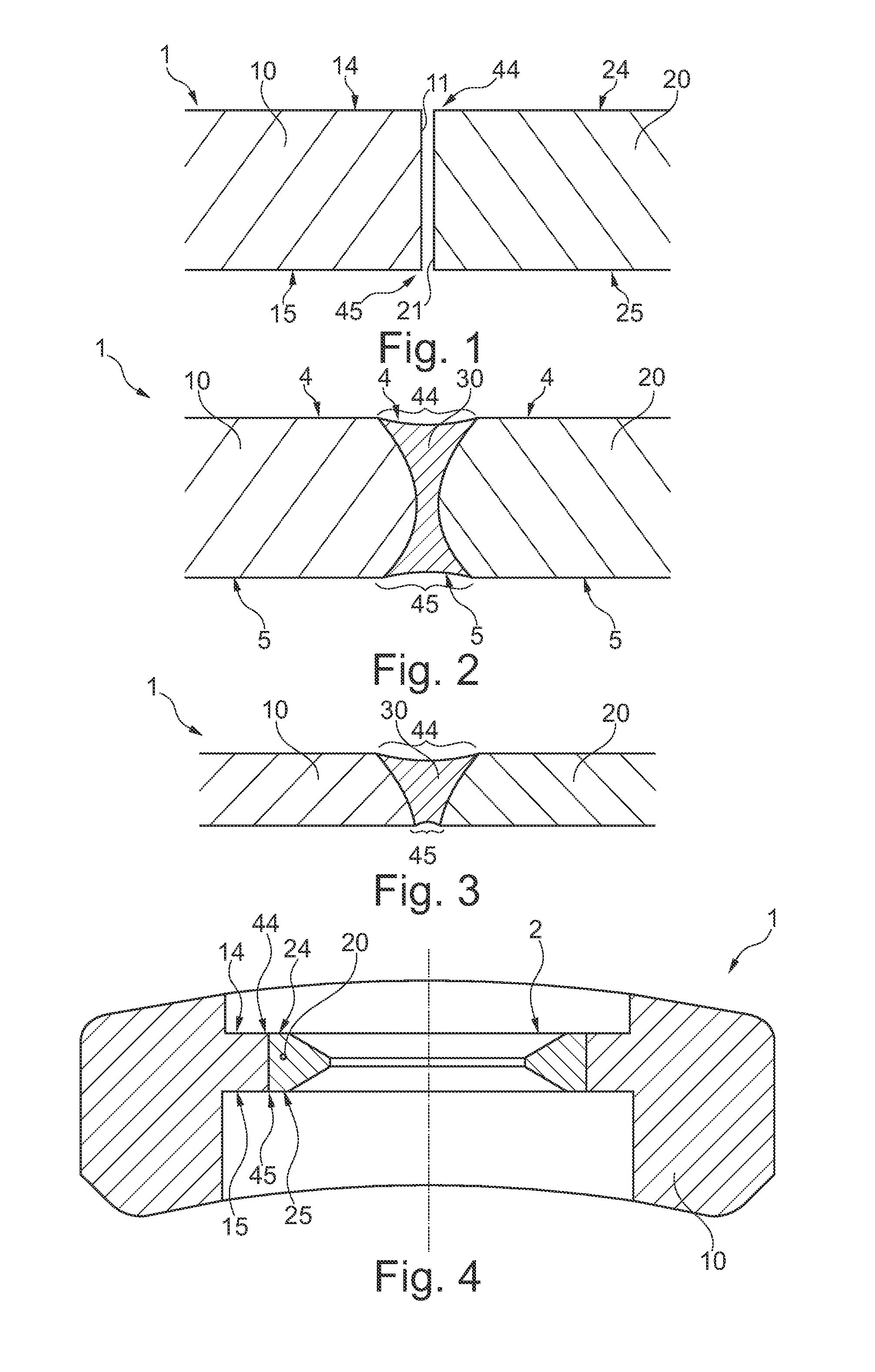
[0043]FIG. 1 illustrates a bone plate 1 having a first plate portion 10 and a second plate portion 20. The first plate portion 10 has a first top surface 14 and a first bottom surface 15. The second plate portion 20 has a second top surface 24 and a second bottom surface 25. FIG. 1 illustrates the first plate portion and the second plate portion in an unjoined or unwelded condition, wherein the both portions 10 and 20 are illustrated with a gap for sake of a clear illustration. However, it should be noted that the both plate portions 10 and 20 also in an unwelded condition may be positioned abutting to each other, so that a first wall portion 11 of the first plate portion 10 abuts to a second wall portion 21 of the second plate portion. The both top surfaces 14, 24 form a connecting line 44, wherein the both bottom surfaces 15 and 25 form a bottom connecting line. The material of the first plate portion has a higher material yield strength than the second plate portion 20. Thus, it ...


PUM


Abstract

A hybrid bone plate has a first plate portion, having a first top surface and a first bottom surface and comprises a hard titanium alloy. A second plate portion has a second top surface and a second bottom surface and comprises a pure titanium or a soft titanium alloy. The first plate portion has a higher material yield strength than the second plate portion. The first plate portion and the second plate portion are connected to each other at a transition region by for example welding wherein in the transition region the first top surface and the second top surface together form a closed top integral surface and the first bottom surface and the second bottom surface together form a closed bottom integral surface.

Description

FIELD OF THE INVENTION[0001]The present invention relates to a hybrid bone plate, and in particular to a hybrid bone plate, which allows for a more flexible application for a wide variety of bone geometries.BACKGROUND OF THE INVENTION[0002]Bone plates are used for osteosynthesis applications, in particular for several kinds of fractures of bones. For this purpose, a wide variety of different bone plate geometries have been provided in order to meet the individual bone geometry and fracture situation of the patients to be treated.[0003]To allow a flexible application of a bone plate, several approaches have been made, in order to allow a flexible orientation of for example screws for fixing the bone plate to the bone. For example, particularly designed threads have been provided in bore holes of a bone plate which allow for a variety of orientations of a bone screw when mounted to the bone and the bone plate. Further, bone plates have been proposed including inserts of an elastic mat...

Claims


Application Information

Patent Timeline
IPC IPC(8): A61B17/80
CPCA61B17/80A61B17/8047A61B2019/4868A61B17/8085A61B17/8057A61B2090/0813A61B17/8023A61B17/8061
Inventor VON WIEDING, HOLGERRIEMER, ROSEGRIMM, MICHELSCHNEIDER, JORG
Owner STRYKER EURO OPERATIONS HLDG LLC
Why Eureka
Try Eureka