Vehicle charging system and vehicle charging method

Active Publication Date: 2012-03-29
MITSUBISHI ELECTRIC CORP
View PDF6 Cites 18 Cited by
  • Summary
  • Abstract
  • Description
  • Claims
  • Application Information

AI Technical Summary

Benefits of technology

[0008]The present invention has been made to solve the above-mentioned problem, and therefore has an object to provide a vehicle charging system and a vehicle charging method, which are capable of supplying power to a control section to charge a drive battery, even when it is impossible to supply power from the batteries included in a vehicle.
[0009]According to the present invention, there is provided a vehicle charging system, including: a drive battery for supplying power to a running motor of a vehicle; an auxiliary battery for supplying power to auxiliary equipment of the vehicle; and a drive battery charging device for charging the drive battery by receiving power from an external power source, in which: the drive battery charging device includes: a control section; and a power source circuit for supplying power to the control section; and the power source circuit includes: power conversion means which is connected to a plurality of power sources including the external power source, and supplies power from at least one of the plurality of power sources to the control section; and switching means for switching ON/OFF of c

Problems solved by technology

Thus, the drive battery charging device cannot opera

Method used


Image

  • Vehicle charging system and vehicle charging method
  • Vehicle charging system and vehicle charging method

Examples


embodiment 1

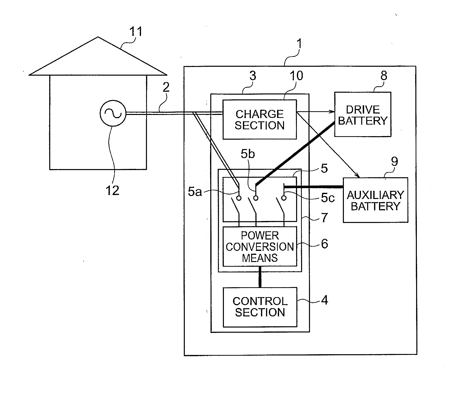
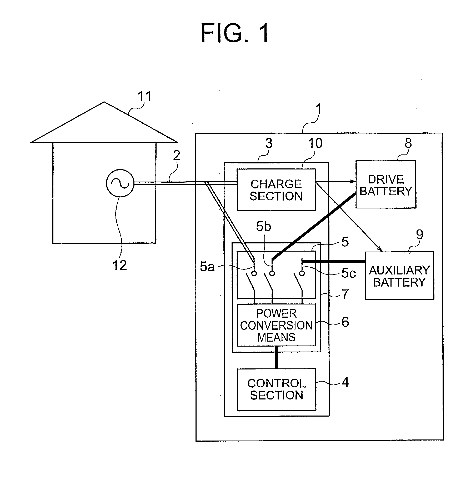
[0012]FIG. 1 is a block diagram illustrating an overall configuration of a vehicle charging system 1. In FIG. 1, the vehicle charging system 1 includes a connection cable 2, a drive battery charging device 3, a drive battery 8, and an auxiliary battery 9.

[0013]The vehicle charging system 1 is mounted in a vehicle such as an automobile. The vehicle runs on a running motor (not shown) with the use of power from the drive battery 8. The auxiliary battery 9 supplies power to auxiliary equipment (lamp, wiper motor, power window motor, microcomputer, and the like) provided on the vehicle.

[0014]At a house 11 or the like, an external power source 12 such as a commercial power source is provided. The vehicle charging system 1 is connected to the external power source 12 via the connection cable 2.

[0015]The drive battery charging device 3 includes a control section 4, a power source circuit 7, and a charge section 10. The power source circuit 7 includes power source switching means 5 and powe...


PUM


Abstract

A vehicle charging system (1) includes: a connection cable (2) for supplying power from the external power source (12) such as a commercial power source; the drive battery (8); an auxiliary battery (9); and a drive battery charging device (3). The drive battery charging device (3) includes a power source circuit (7) connected to the external power source (12), the drive battery (8), and the auxiliary battery (9). Power from at least one of the external power source (12), the drive battery (8), and the auxiliary battery (9) is supplied to the control section (4). Operation of the control section (4) becomes possible with the supplied power. Accordingly, under control of the control section (4), a charge section (10) charges the drive battery (8) and the auxiliary battery (9) using power from the external power source (12).

Description

BACKGROUND OF THE INVENTION[0001]1. Field of the Invention[0002]The present invention relates to a vehicle charging system and a vehicle charging method, and more particularly, to a vehicle charging system and a vehicle charging method for charging a drive battery of a vehicle which is capable of being charged from outside of the vehicle.[0003]2. Description of the Related Art[0004]In recent years, there have been developed an electric vehicle and a hybrid vehicle as environmentally-friendly vehicles. Such vehicles are provided with a drive battery and a running motor, and run on the running motor with the use of power from the drive battery. Therefore, it is necessary to charge the drive battery. The drive battery can be charged by receiving power from an external power source such as a commercial power source.[0005]When charging is performed, a control power source circuit (control section) controls a drive battery charging device. Therefore, supply of power to the control power s...

Claims


Application Information

Patent Timeline
IPC IPC(8): H02J7/00B60L9/12B60R16/04
CPCB60L11/1811B60L11/1868H02J7/02Y02T90/127Y02T10/7088Y02T10/7066Y02T90/14Y02T10/7005Y02T10/7072B60L53/20B60L58/20Y02T10/70H02J5/00Y02T90/12
Inventor TAKIKITA, MAMORU
Owner MITSUBISHI ELECTRIC CORP
Why Eureka
Try Eureka