
Inductive Current Sensor

a technology of inductive current and sensor, which is applied in the field of electric sensors, can solve the problems of high cost of clamping probe or split-core probe, low efficiency of inductive current measurement, and inability to measure power, etc., and achieve the effect of facilitating magnetic field through coil, facilitating detection of voltage in coil, and facilitating magnetic field

Inactive Publication Date: 2012-03-29
WOBSCHALL DAROLD
View PDF5 Cites 20 Cited by
  • Summary
  • Abstract
  • Description
  • Claims
  • Application Information

AI Technical Summary

Benefits of technology

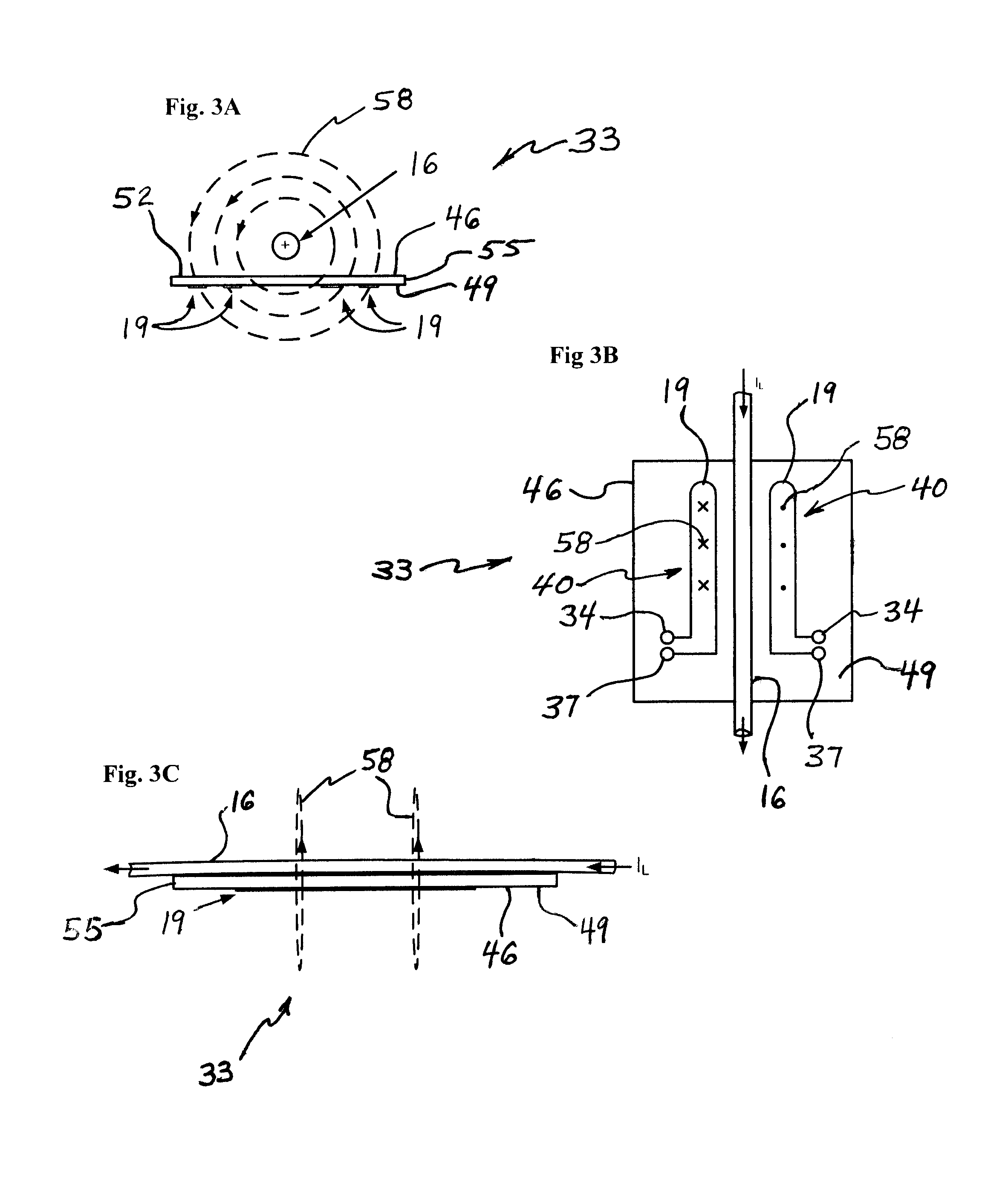
[0009]A magnetic body may be provided to facilitate the magnetic field from the lead in reaching the coil. The magnetic body may have a cavity through which the lead extends. In one embodiment of the invention, the magnetic body is “E” shaped. A magnetic strip may be positioned so as to sandwich the coil between the strip and the substrate, and thereby further facilitate the magnetic field through the coil.
[0010]A second pickup coil may be included. The second pickup coil may be attached to the substrate and proximately placed near the lead. The magnetic field created by electricity moving through the lead extends through the first coil in a first direction, and through the second coil in a second direction. The two coils may be electrically connected to each other in order to add their respective voltages, and thereby facilitate detection of the voltage in the coils.

Problems solved by technology

However, this method of measuring power is not often desirable because the wire carrying the current (in this case, the conductor) must be broken to install the doughnut-shaped current sensor.
However the cost of a clamp-on probe or a split-core probe is high, and such devices are often too bulky for permanent installation.

Method used


Image

  • Inductive Current Sensor
  • Inductive Current Sensor
  • Inductive Current Sensor

Examples


Embodiment Construction

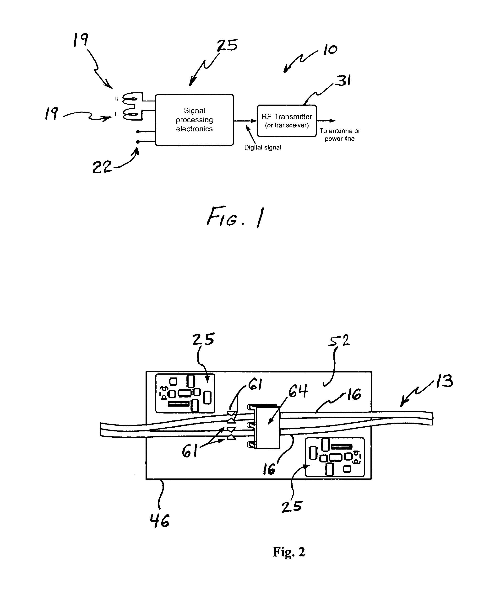
[0026]The invention is an inductive current sensor, which may be included in a power meter. FIG. 1 is a block diagram of a power meter 10 that is in keeping with the invention. The power meter 10 is intended for use in determining the power being delivered by a conductor 13. In most instances the conductor 13 is comprised of two wire-leads 16, and these leads 16 will usually be electrically insulated from each other. Often, such a conductor 13 is originally supplied such that the insulation is a unitary body that maintains a desired distance between the leads 16. The insulation extending between the leads 16 can be cut or torn, if desired.

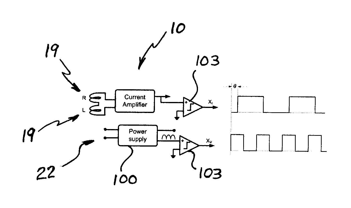
[0027]The power meter 10 of FIG. 1 includes at least one current pickup 19 and at least one voltage pickup 22. The current pickup 19 and voltage pickup 22 are electrically connected to signal processing electronics 25, which may include a microcontroller 28, for signal processing. An output from the microcontroller 28 may be connected to a transmit...


PUM


Abstract

A power meter is disclosed. The power meter may be used to determine the electric power being delivered by a conductor. In one such power meter there is a substrate, an inductive pickup coil attached to the substrate, a conductor, and a detector. The pickup coil may be printed on the substrate.

Description

CROSS-REFERENCE TO RELATED APPLICATION[0001]This application claims the benefit of priority to U.S. provisional patent application Ser. No. 61 / 386,685, filed on Sep. 27, 2010.FIELD OF THE INVENTION[0002]The present invention relates to electrical sensors for measuring power delivered by a conductor.BACKGROUND OF THE INVENTION[0003]There are many methods and devices which can be used to measure the power being delivered by an electrical conductor. In one such device, often referred to as a shunt, a resistor having a known resistance is placed in the conductive path, and the voltage across this resistor is measured. This is a simple, accurate method of determining the power being delivered via the conductor. However, by using the shunt, the conductive path is not isolated from the power measuring equipment. Also, an existing conductor must be cut in order to insert the shunt into the conductor.[0004]Another method uses a current transformer. A primary winding is inserted into the cond...

Claims


Application Information

Patent Timeline
Patent Type & Authority Applications(United States)
IPC IPC(8): G01R19/00G01R1/20
CPCG01R21/06G01R15/181
Inventor WOBSCHALL, DAROLD
Owner WOBSCHALL DAROLD
Learn More