
Multi-beam telecommunication antenna onboard a high-capacity satellite and related telecommunication system

a telecommunication antenna and satellite technology, applied in the field of telecommunication antennas, can solve the problems of deteriorating the efficiency of the antenna, notable and unwanted loss of the telecommunication system capacity, and the capacity of the current platform and launch vehicle does not make it possible to consider

Active Publication Date: 2012-03-29
CENT NAT DETUD SPATIALES C N E S
View PDF4 Cites 15 Cited by
  • Summary
  • Abstract
  • Description
  • Claims
  • Application Information

AI Technical Summary

Benefits of technology

[0040]the reflector is a portion of a dish shifted relative to the feed block so as to prevent masking of the secondary beams by the feed block, and

Problems solved by technology

In this case, it would have been necessary to produce smaller illumination sources, which would have deteriorated the antenna's efficiency, in particular by increasing energy losses by spillover, typically from 4 to 6 dB.
Since the C / I performance remains in the vicinity of 12 dB, the efficiency loss of the antenna would have caused a deterioration of the Effective Isotropic Radiated Power (EIRP), which would amount to a notable and unwanted loss of capacity of the telecommunications system.
However, the contribution capacities of the current platforms and launch vehicles do not make it possible to consider solutions with multiple reflectors having a diameter greater than 3 or 3.5 meters.
Moreover, when the number of beams increases, the observed C / I becomes very low and, despite the use of frequencies, the capacity decreases.
The technical problem is to increase the transmission capacity of the satellite under operating conditions of the satellite identical to those presented for the limit configuration in terms of power consumed by the multimedia payload of the satellite, frequency band allocated to the downlink, characteristics of the terminals and mating limitation within a satellite intended to enter a fairing of a launch vehicle.

Method used


Image

  • Multi-beam telecommunication antenna onboard a high-capacity satellite and related telecommunication system
  • Multi-beam telecommunication antenna onboard a high-capacity satellite and related telecommunication system
  • Multi-beam telecommunication antenna onboard a high-capacity satellite and related telecommunication system

Examples


Embodiment Construction

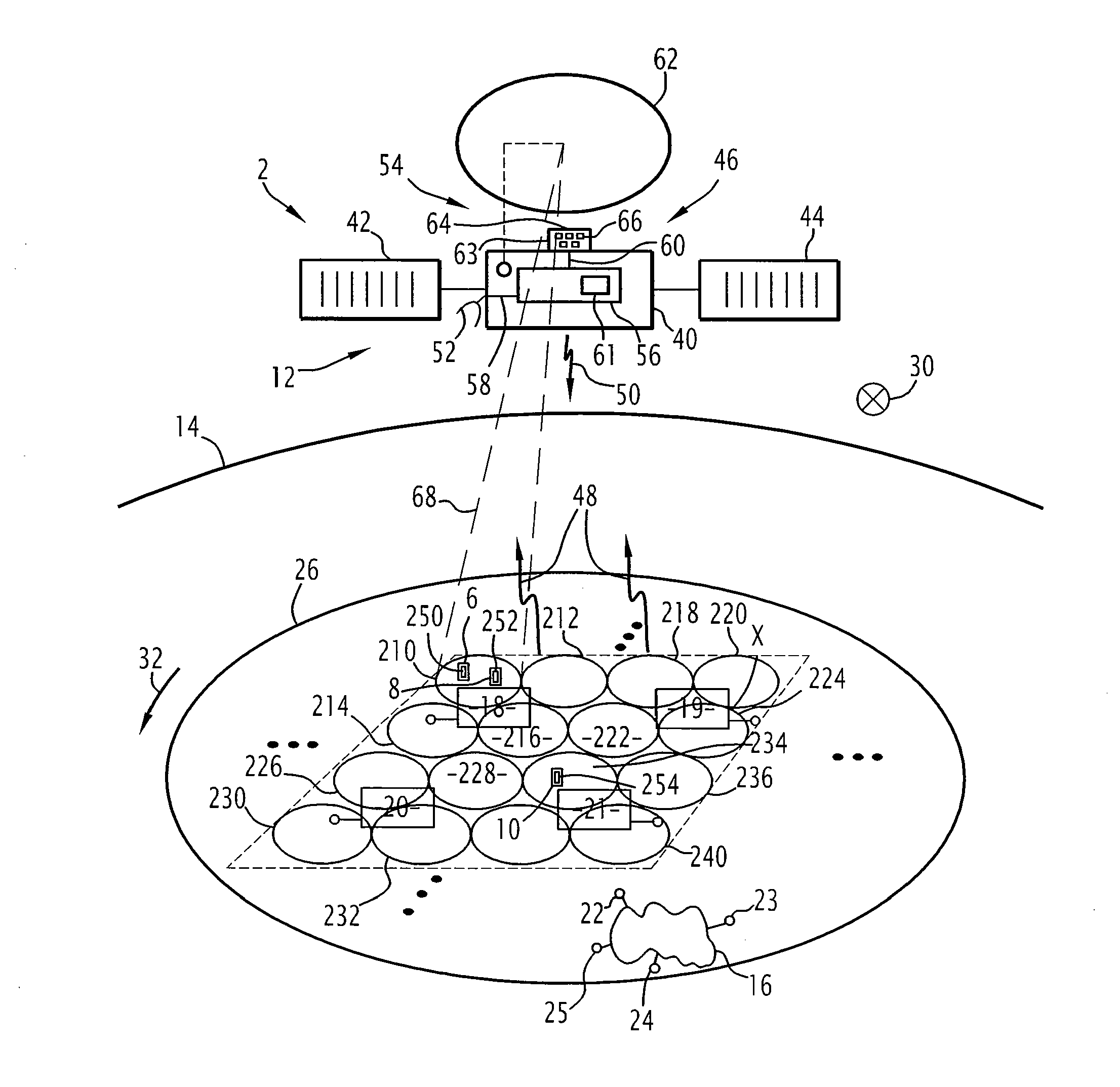
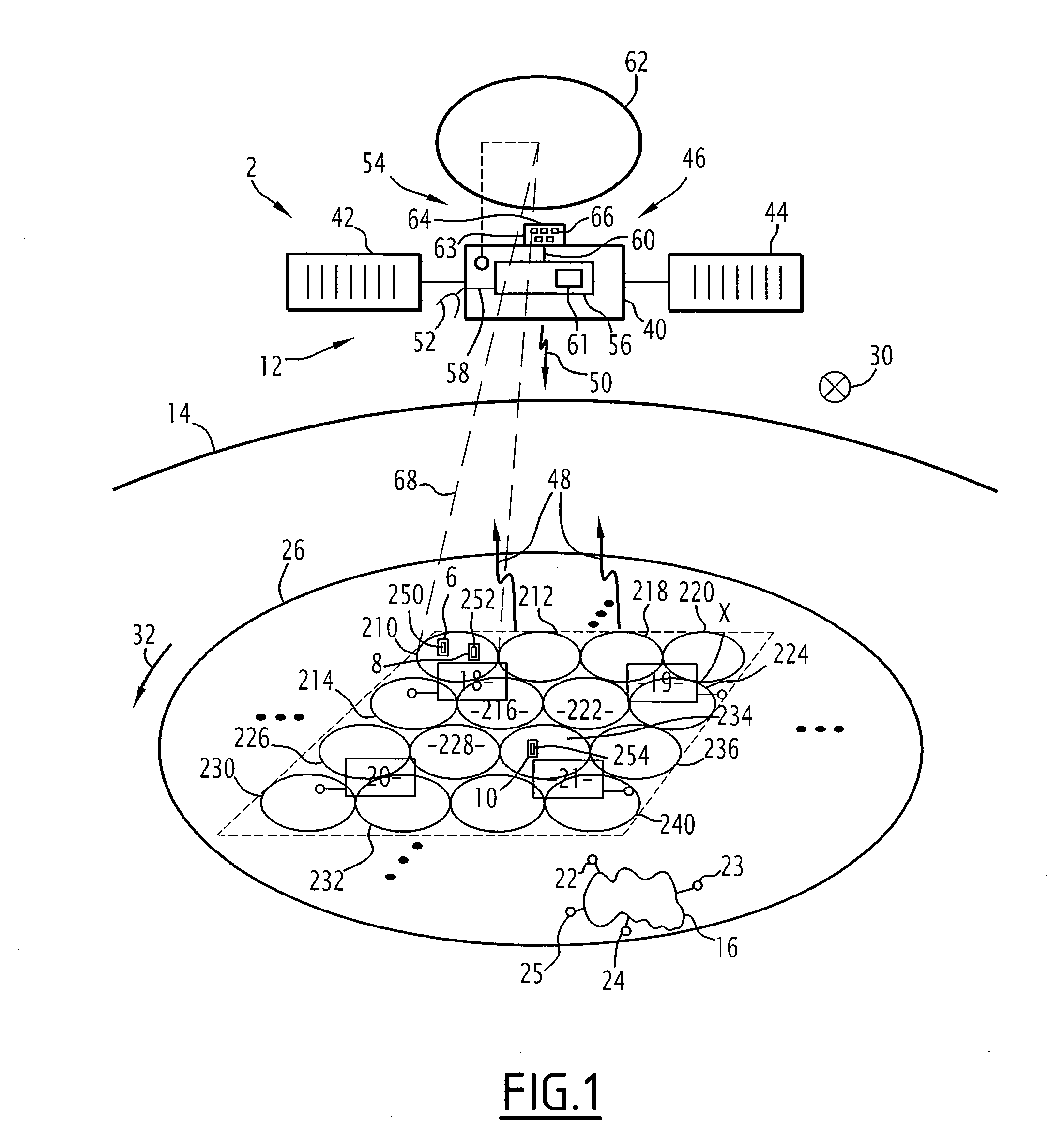
[0081]According to FIG. 1, a telecommunication system 2, here for multimedia services, with a satellite comprises a set 4 of multimedia terminals 6, 8, 10, a satellite 12 in geostationary orbit around the Earth 14, a multimedia ground infrastructure 16, and several gateways 18, 19, 20, 21 to the satellite, each connected to the ground infrastructure 16 by a different communication link, not shown, in respective connection terminals 22, 23, 24, 25.

[0082]The multimedia system 2 is supposed to serve a small geographical coverage area 26, between 500,000 km2 and 1,500,000 km2.

[0083]Typically, this corresponds for the northern hemisphere to one, two or three countries each the size of France.

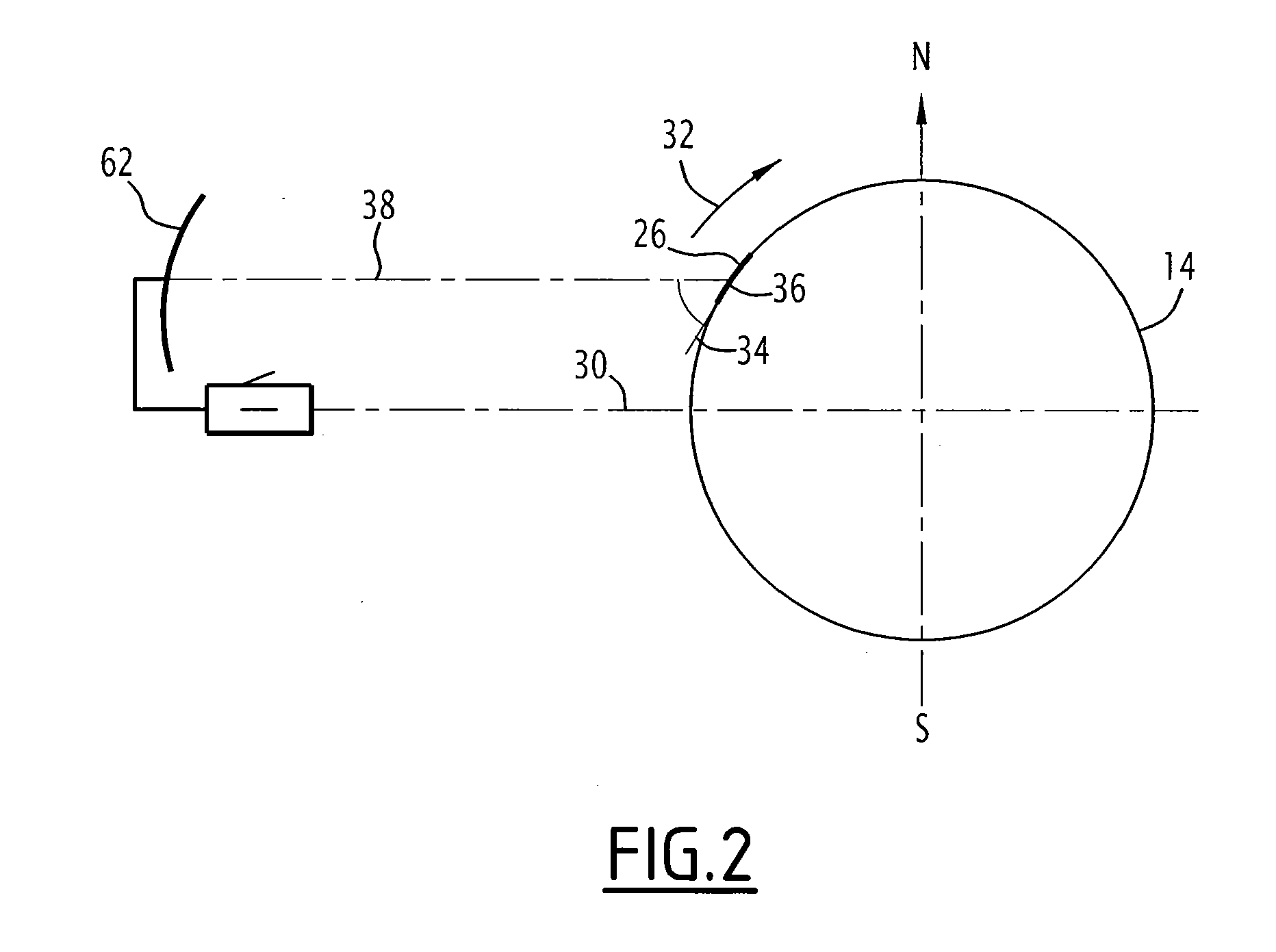
[0084]Here, as an example, the coverage area 26 for the telecommunication service is France, and it is between the meridians situated at 5° west and 6° east, between latitudes 43° north and 51° north.

[0085]The geostationary satellite 12 in geostationary orbit around the Earth 14 is placed on a first ...


PUM


Abstract

A high-throughput multi-beam telecommunication antenna is configured to cover a geographical area from a geostationary orbit.It comprises a single reflector and a feed block configured so that each elementary feed is able to generate a different unique beam, the angular separation of any two adjacent primary beams is substantially equal to the angular separation of any two adjacent secondary beams, and the spillover energy losses associated with each source are between 3 and 10 dB, preferably between 3 and 7.5 dB.

Description

CROSS-REFERENCE TO RELATED APPLICATIONS[0001]This application claims benefit of French patent application serial number 10 57193, filed Sep. 10, 2010, which is herein incorporated by reference.BACKGROUND OF THE INVENTION[0002]1. Field of the Invention[0003]The present invention relates to a telecommunication antenna intended to be placed onboard a telecommunication satellite, a payload of a telecommunication satellite comprising the antenna, and a telecommunication system using the payload and therefore the telecommunication antenna.[0004]2. Description of the Related Art[0005]In general and to date in the case of spatial telecommunication using geostationary satellites for the transmission of Ka-band multimedia services, one seeks to broaden the coverage provided by the telecommunication antenna(e) onboard the satellite and to increase the transmission capacity while ensuring a high C / I performance (payload to interfering signal ratio).[0006]To obtain the expected system level perf...

Claims


Application Information

Patent Timeline
IPC IPC(8): H01Q1/28
CPCH01Q25/007H01Q13/02H01Q1/28H01Q1/288H01Q19/17
Inventor PALACIN, BAPTISTEDEPLANCQ, XAVIER
Owner CENT NAT DETUD SPATIALES C N E S
Learn More