Shipborne satellite communication system and method for shipborne antenna to track satellite

A satellite communication system and satellite communication technology, applied in the field of shipborne satellite communication systems and shipborne antenna tracking satellites, can solve the problems of short antenna life, low stability, complicated installation, etc., and achieve low latency and real-time attitude control. Good performance and high precision

Inactive Publication Date: 2017-04-26
中云卫星通信有限公司
View PDF7 Cites 14 Cited by
  • Summary
  • Abstract
  • Description
  • Claims
  • Application Information

AI Technical Summary

Benefits of technology

This patented technology uses an MIC (Microelectromechanics Integrated Circuit) sensor system, a device called a navigation subsystem or servomotor controller, along with other components like sensors and actuators used on board the vessel's surface itself. These systems help keep the vehicle stable while navigating through space. They are designed to provide precise positioning over long periods without any delays due to their small size but still have quick response times.

Problems solved by technology

The technical problem addressed during this patented process relates to improving the performance or lifespan of mobile phone mounted on board (MBO) platforms when they are moving around over rough seas caused by changing their orientation relative to other objects like rocks.

Method used


Image

  • Shipborne satellite communication system and method for shipborne antenna to track satellite
  • Shipborne satellite communication system and method for shipborne antenna to track satellite
  • Shipborne satellite communication system and method for shipborne antenna to track satellite

Examples


Embodiment 1

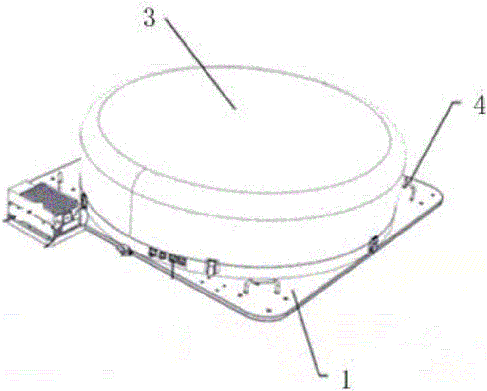
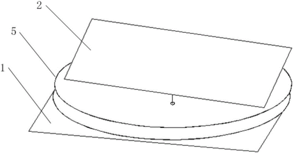
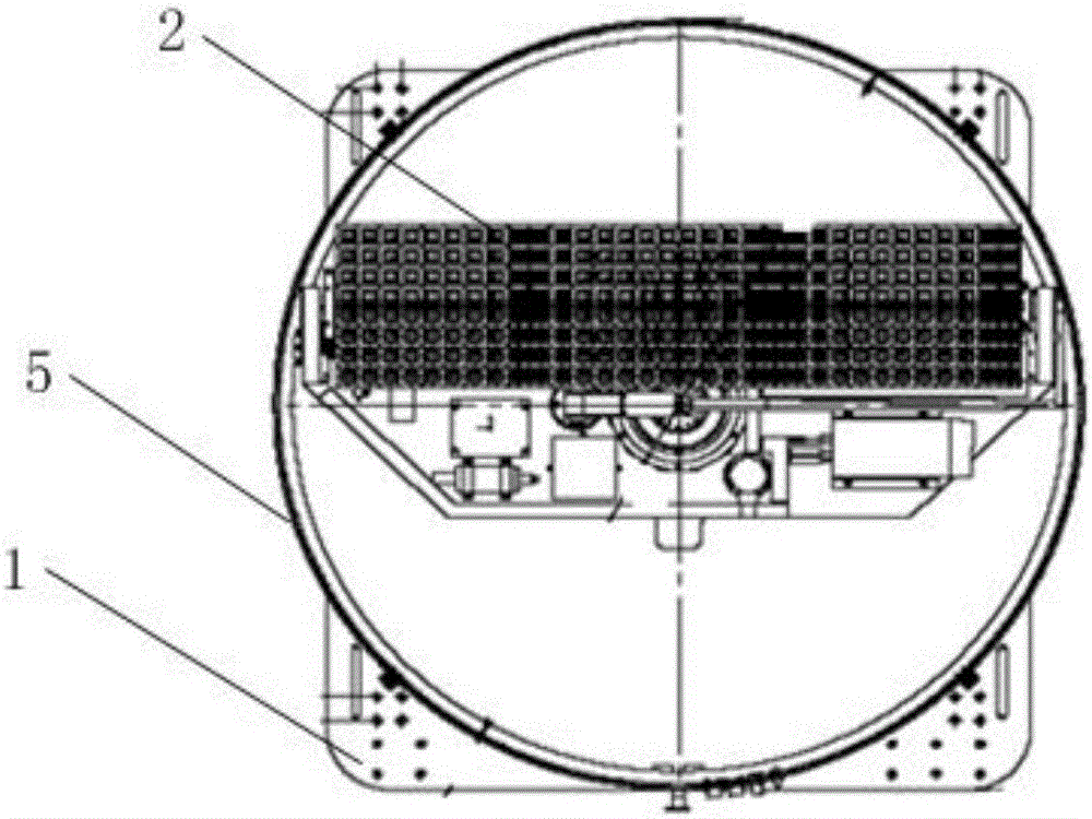
[0036] like Figures 1 to 3 As shown, the present embodiment provides a shipborne satellite communication system, which includes an antenna base 1, a satellite communication antenna 2, a MEMS inertial measurement unit and a servo drive unit; wherein the satellite communication antenna 2, the MEMS inertial measurement unit and the servo drive unit The units are all installed on the antenna base 1; the satellite communication antenna 2 is used to send and receive Ku or L-band communication signals of geosynchronous orbit communication satellites or low-inclination geosynchronous orbit communication satellites; the MEMS inertial measurement unit is used to obtain the attitude parameters of the hull; the servo The drive unit is used to drive the satellite communication antenna to rotate, so as to adjust the azimuth angle, elevation angle and polarization angle of the satellite communication antenna.

[0037] The satellite communication antenna 2, MEMS inertial measurement unit and ...

Embodiment 2

[0043] Based on the shipborne satellite communication system provided by Embodiment 1, such as Figure 4 As shown, the present embodiment provides a method for a shipborne satellite communication antenna to track a satellite, which includes:

[0044]S1: Use GPS to obtain the geographic longitude and latitude where the hull is located, and use MEMS inertial measurement unit to obtain the attitude parameters of the hull;

[0045] S2: The attitude calculation unit performs coordinate transformation and calculation according to the star alignment parameters of the target satellite, the geographic longitude and latitude of the hull, and the attitude parameters of the hull, and calculates the azimuth angle required for the antenna to align with the target satellite, Pitch and polarization angles;

[0046] S3: The control unit controls the servo drive unit to drive the satellite communication antenna to rotate according to the calculated azimuth angle, elevation angle and polarizati...


PUM

PropertyMeasurementUnit
Heightaaaaaaaaaa
Caliberaaaaaaaaaa

Abstract

The present invention relates to a shipborne satellite communication system and a method for a shipborne antenna to track a satellite. The shipborne satellite communication system comprises an antenna base, a satellite communication antenna, an MEMS inertial measurement unit and a servo driving unit; the satellite communication antenna is arranged at the antenna base and is used for receiving and transmitting the Ku or L-band communication signals of a geostationary orbit communication satellite or a small-angle geostationary orbit communication satellite; and the MEMS inertial measurement unit is arranged on the antenna base and is used for acquiring the attitude parameters of a hull; and the servo driving unit is arranged on the antenna base and is used for driving the satellite communication antenna to rotate so as to adjust the azimuth angle, pitch angle and polarization angle of the satellite communication antenna. With the shipborne satellite communication system and the method for the shipborne antenna to track the satellite of adopted, the satellite communication antenna can accurately track the satellites in a surge state, the installation complexity of the MEMS inertial measurement unit is decreased. The overall structure of the shipborne satellite communication system is compact, and the size of the shipborne satellite communication system is small.

Description


Claims


Application Information

Patent Timeline
Owner 中云卫星通信有限公司
Why Eureka
Try Eureka