System and method for background phase correction for phase contrast flow images

a technology of contrast magnetic resonance and background phase, applied in the field of background phase correction of phase contrast magnetic resonance images, can solve the problems of significant errors in mean volume flow, stroke volume, cardiac output, and background is not uniform throughout the region

Inactive Publication Date: 2012-03-29
SIEMENS HEALTHCARE GMBH
View PDF11 Cites 16 Cited by
  • Summary
  • Abstract
  • Description
  • Claims
  • Application Information

AI Technical Summary

Benefits of technology

The technical effect of this patent is that it describes a way for computers to analyze images by looking at individual pixel points and organizing them into larger groups based on their appearance. By doing this, the computer can identify specific patterns or shapes within the image more easily. This helps improve the accuracy and efficiency of analyzing images.

Problems solved by technology

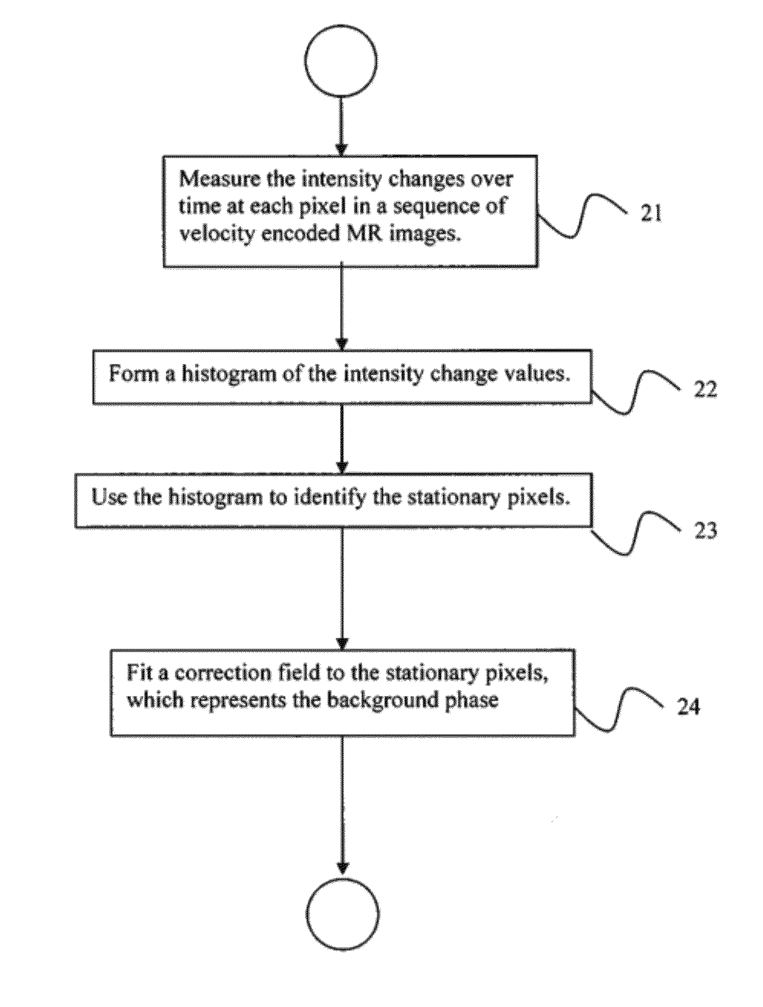
The technical problem addressed in this patent relates to correcting velocity-coded phase images for errors caused by non-compensated eddy currents and gradients in magnetic resonance imaging (MRI) machines. A common method involves defining a single reference region to estimate the background phase, which can cause significant errors when determining flow measurements. Another proposed method involves fit a surface through stationary pixels in the image, but further improvements are needed to improve accuracy.

Method used


Image

  • System and method for background phase correction for phase contrast flow images
  • System and method for background phase correction for phase contrast flow images
  • System and method for background phase correction for phase contrast flow images

Examples


Embodiment Construction

[0021]Exemplary embodiments of the invention as described herein generally include systems and methods for correcting background phase in phase contrast magnetic resonance (MR) images. Accordingly, while the invention is susceptible to various modifications and alternative forms, specific embodiments thereof are shown by way of example in the drawings and will herein be described in detail. It should be understood, however, that there is no intent to limit the invention to the particular forms disclosed, but on the contrary, the invention is to cover all modifications, equivalents, and alternatives falling within the spirit and scope of the invention.

[0022]As used herein, the term “image” refers to multi-dimensional data composed of discrete image elements (e.g., pixels for 2-dimensional images and voxels for 3-dimensional images). The image may be, for example, a medical image of a subject collected by computer tomography, magnetic resonance imaging, ultrasound, or any other medica...


PUM


Abstract

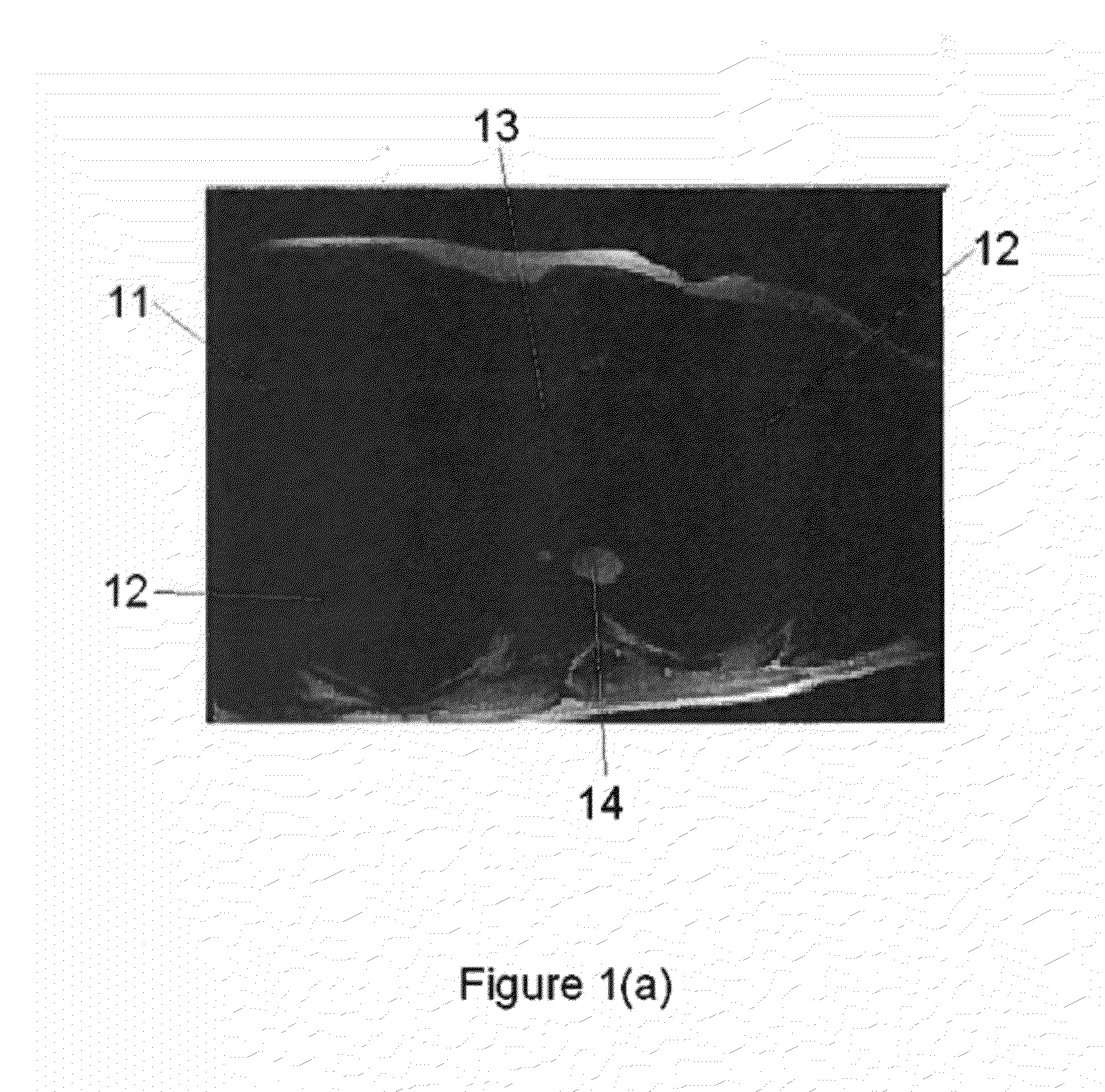
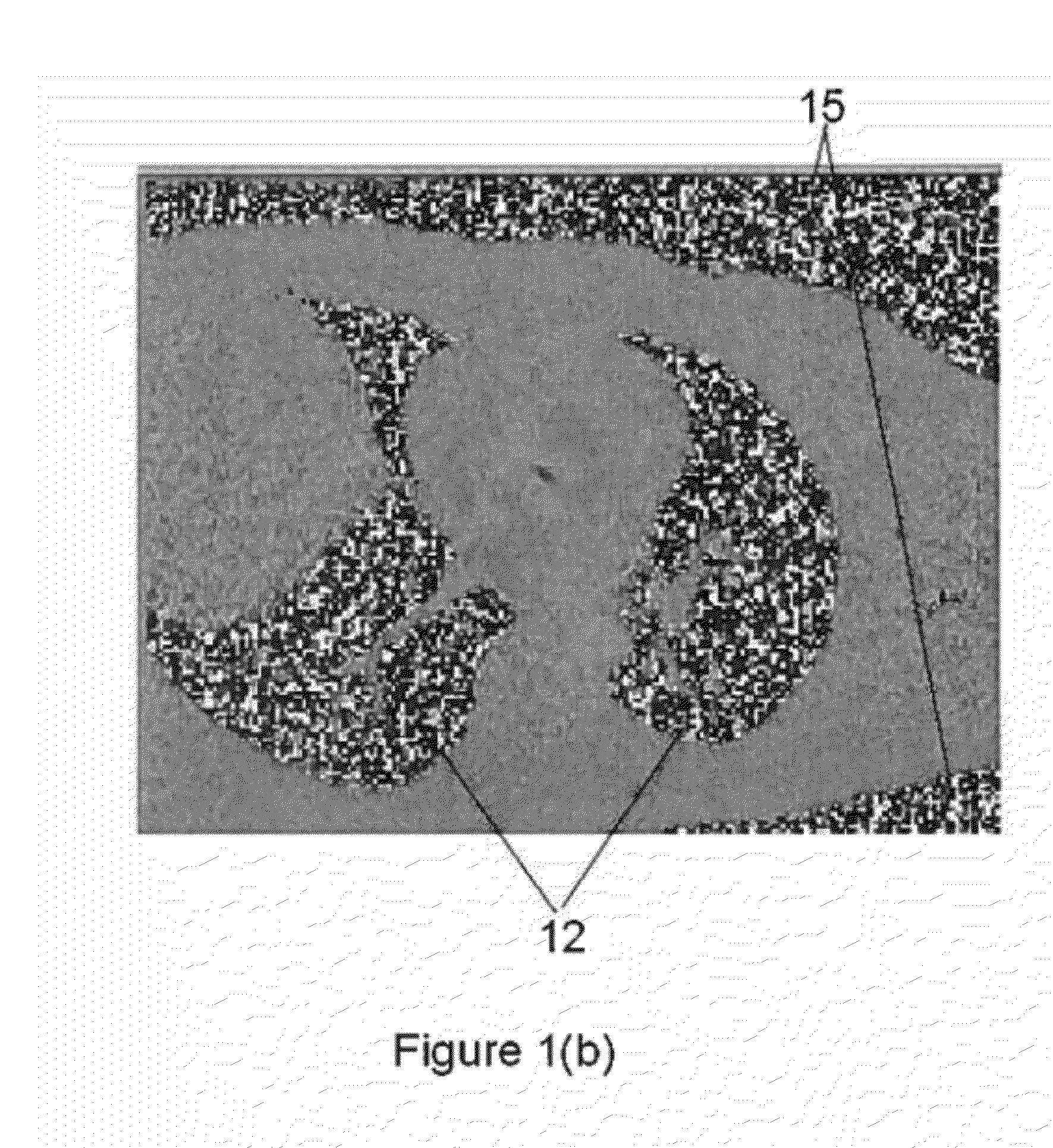
A method for correcting the background phase in magnetic resonance phase contrast flow images includes providing a time series of velocity encoded magnetic resonance images of a patient, where the time series of velocity encoded images comprises for each time point a phase contrast image where a pixel intensity is proportional to a flow velocity, measuring a change of intensity for each pixel over the time series of phase contrast images, identifying pixels with a low measure of temporal change as stationary pixels, and calculating a correction field for the stationary pixels, where the correction field represents a background phase to be subtracted from the phase contrast image.

Description


Claims


Application Information

Patent Timeline
Owner SIEMENS HEALTHCARE GMBH
Why Eureka
Try Eureka