Cycle slip location and correction

a technology of cycle slip and correction, applied in the field of optical communication systems, can solve the problems of significant increase the frequency mismatch beyond this amount, erroneous interpretation of every symbol, and a finite line width of the laser

Active Publication Date: 2010-06-03
CIENA
View PDF11 Cites 51 Cited by
  • Summary
  • Abstract
  • Description
  • Claims
  • Application Information

AI Technical Summary

Problems solved by technology

However, as is known in the art, such semiconductor lasers exhibit a finite line width and non-zero phase noise.
Short period phase noise in both the transmitter and LO laser may significantly increase the frequency mismatch beyond this amount.
This can result in the erroneous interpretation of every symbol (and thus all data) following the cycle-slip.
The presence of a cycle slip means that every data symbol between the cycle slip and the next SYNC burst will be erroneously decoded.
Naturally, the portion of the FEC budget assigned to cycle slips reduces the remaining FEC budget that is available for correcting errored symbols due to noise.

Method used


Image

  • Cycle slip location and correction
  • Cycle slip location and correction
  • Cycle slip location and correction

Examples


Embodiment Construction

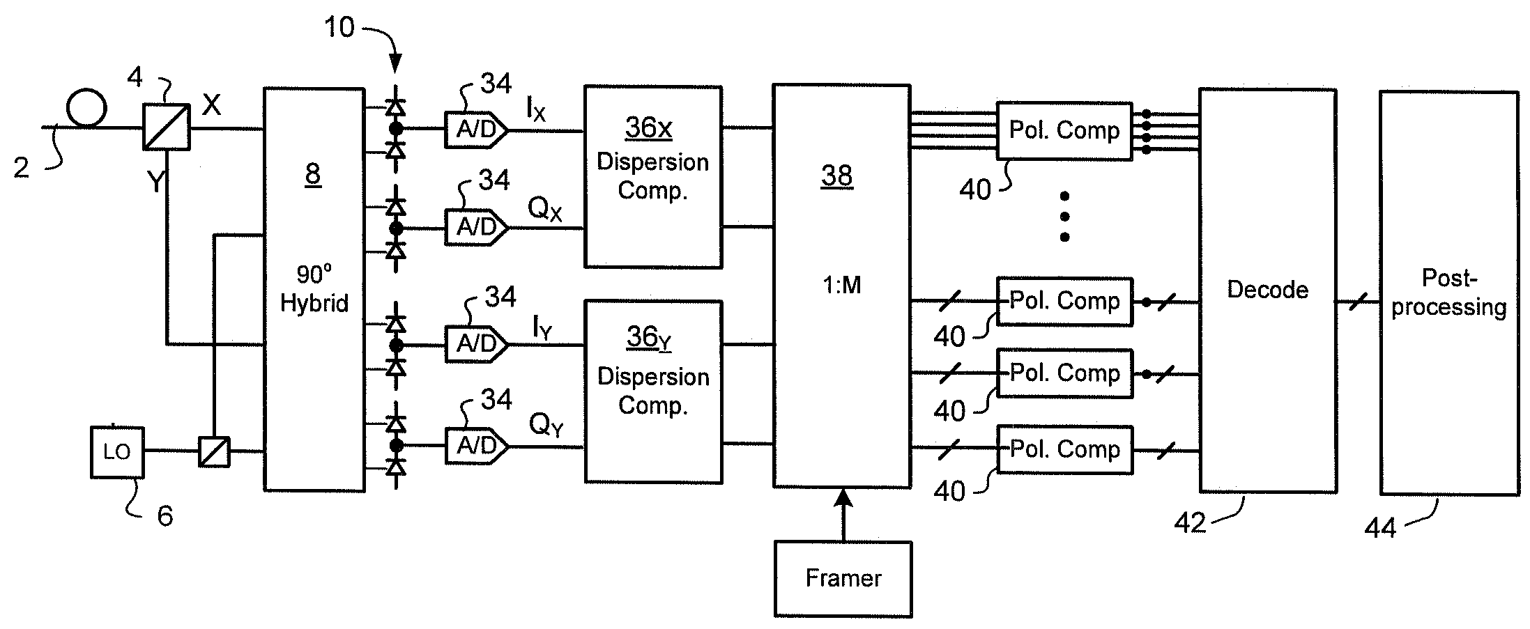
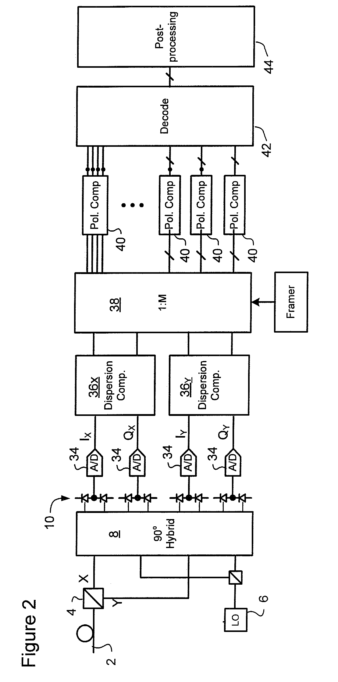
[0021]In very general terms, the present invention builds upon the techniques presented in Applicant's co-pending U.S. Patent Application Publication No. US2007 / 0092260 to provide efficient methods for detecting the approximate location of a cycle slip between two successive SYNC bursts, and to apply a correction that reduces the number of symbols affected by the cycle slip. Forward Error Correction (FEC) may then be used to correct residual errored symbols / bits, but the FEC budget that must be assigned to correction of cycle slips is dramatically reduced.

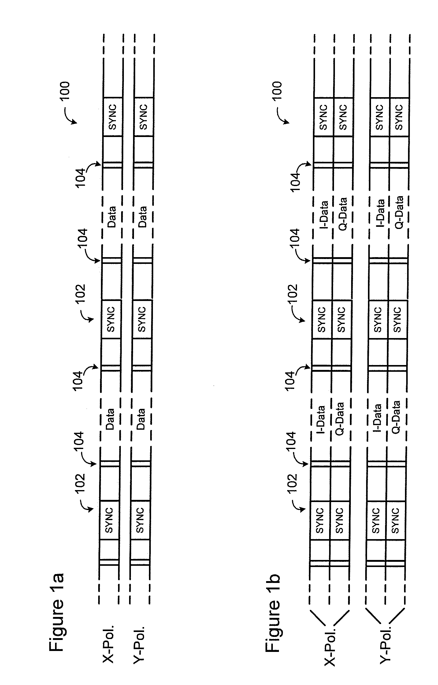
[0022]FIG. 1a schematically illustrates two digital data streams to be transmitted over an optical link. Each data stream 100 is respectively modulated onto X and Y polarizations of the transmitted optical signal. SYNC bursts 102 having a predetermined symbol sequence are embedded in each data stream 100 at regularly spaced intervals. FIG. 1b illustrates an alternative arrangement, in which each of the I and Q components of each tr...


PUM


Abstract

Methods and techniques are disclosed for correcting the effect of cycle slips in a coherent communications system. A signal comprising SYNC bursts having a predetermined periodicity and a plurality of known symbols at predetermined locations between successive SYNC bursts is received. The received signal is partitioned into data blocks. Each data block encompasses at least data symbols and a set of check symbols corresponding to the plurality of known symbols at predetermined locations between a respective pair of successive SYNC bursts in the signal. Each data block is processed to detect a cycle slip. When a cycle slip is detected, the set of check symbols of the data block are examined to identify a first slipped check symbol, and a phase correction applied to data symbols of the data block lying between the first slipped check symbol and an end of the data block.

Description

CROSS-REFERENCE TO RELATED APPLICATIONS[0001]This application is the first application filed for the present invention.MICROFICHE APPENDIX[0002]Not Applicable.TECHNICAL FIELD[0003]The present invention relates generally to optical communication systems, and in particular to systems and methods for cycle slip detection and correction in a coherent receiver.DESCRIPTION OF THE PRIOR ART[0004]In optical communication systems that employ coherent optical receivers, the modulated optical signal received at the coherent receiver is mixed with a narrow-line-width local oscillator (LO) signal, and the combined signal is made incident on one or more photodetectors. The frequency spectrum of the electrical current appearing at the photodetector output(s) is substantially proportional to the convolution of the received optical signal and the local oscillator (LO), and contains a signal component lying at an intermediate frequency that contains data modulated onto the received signal. Consequent...

Claims


Application Information

Patent Timeline
Patent Type & Authority Applications(United States)
IPC IPC(8): H03M13/17G06F11/08
CPCH03M13/333H04B10/6164H04B10/611H03M13/336H04B10/65
Inventor HARLEY, JAMESROBERTS, KIM B.SUN, HAN
Owner CIENA
Why Eureka
Try Eureka