Communication terminal apparatus and radio communication method
a technology of communication terminal and radio communication method, which is applied in the direction of amplitude demodulation, line-fault/interference reduction, baseband system details, etc., can solve the problems of extreme deterioration of reception performance, achieving diversity, and deteriorating reception performance, and achieve excellent reception performan
- Summary
- Abstract
- Description
- Claims
- Application Information
AI Technical Summary
Benefits of technology
Problems solved by technology
Method used
Image
Examples
first embodiment
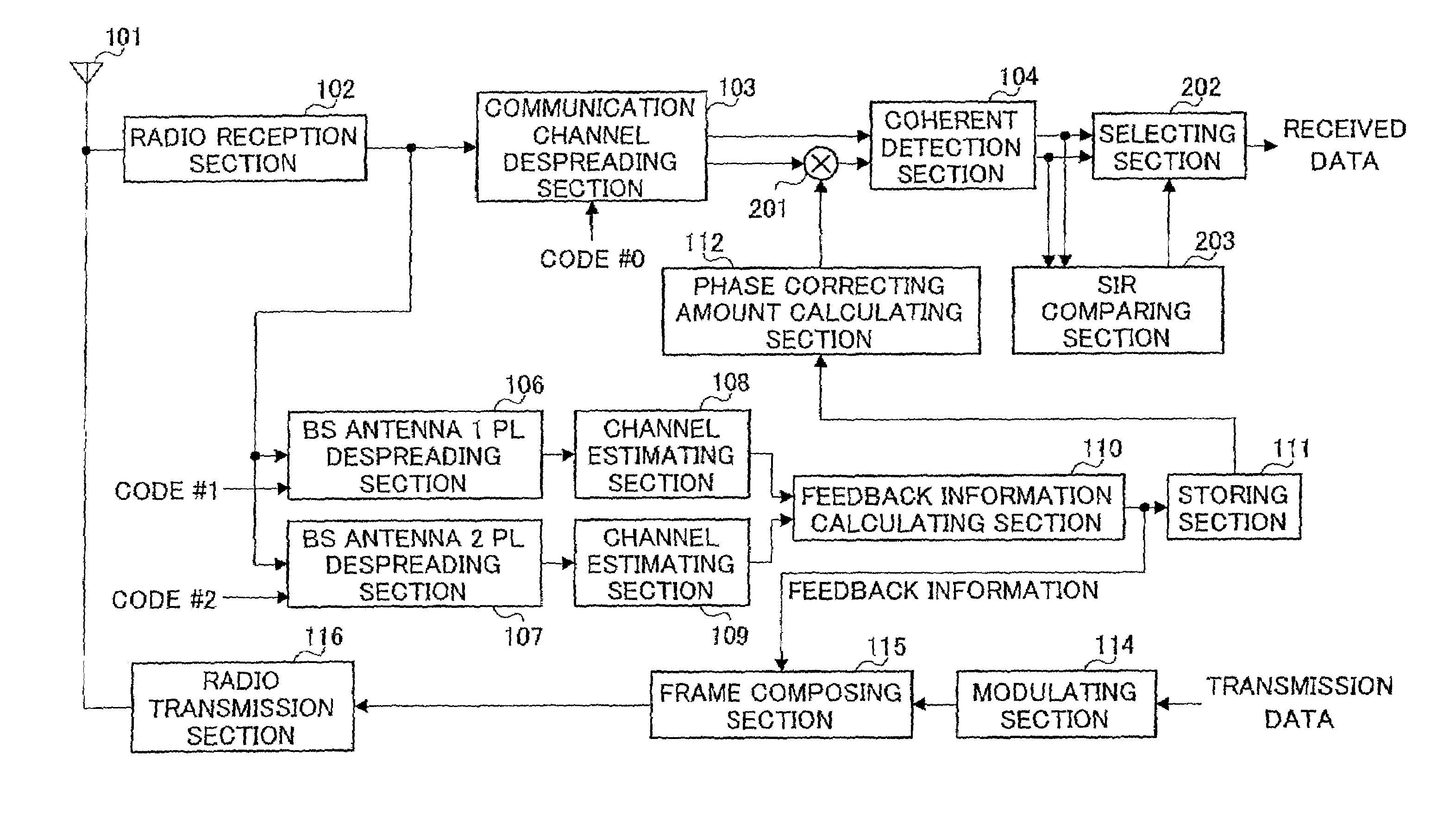
[0033]FIG. 9 is a block diagram illustrating a configuration of a communication terminal apparatus according to the first embodiment of the present invention. A signal received at antenna 101 is output to radio reception section 102. Radio reception section 102 performs predetermined radio reception processing (such as downconverting and A / D conversion) on the received signal.
[0034]A communication channel signal is subjected to the radio reception processing, and is output to communication channel despreading section 103 to be despread with a spreading code #0 used in spreading in a base station apparatus. The signal subjected to despreading (despread signal) is output to coherent detection section 104 and channel estimating section 105.
[0035]Channel estimating section 105 performs channel estimation using the despread signal to obtain a channel estimation value. The channel estimation value is subjected to phase correction using a phase correcting value obtained as described later,...
second embodiment
[0057]It is considered in the first embodiment that when incorrect feedback information arrives at a base station apparatus, a communication terminal apparatus may perform correction that is not necessary. Therefore, in this embodiment, a case will be described that coherent detection is performed on both communication channel signals which are subjected and not subjected to correction, and that one with a higher communication quality is used as a coherent detection result. In addition, a case is explained that as a criterion for evaluating the communication quality, SIR (Signal to Interference Ratio) is used.
[0058]FIG. 10 is a block diagram illustrating a configuration of a communication terminal apparatus according to the second embodiment of the present invention. In FIG. 10, the same sections as in FIG. 9 are assigned the same reference numerals as in FIG. 9, and detailed explanation thereof are omitted.
[0059]The communication terminal apparatus illustrated in FIG. 10 has multip...
third embodiment
[0073]As phase rotation amounts in the closed-loop transmission diversity, angles (0°, +90°, 180° and −90°) are predetermined. In this embodiment, a case is explained that a communication terminal apparatus calculates correcting values always corresponding to all the phase rotation amounts, performs the coherent detection while performing the phase correction, and adopts, as the coherent detection result, one with an excellent communication quality among the coherent detection results. In addition, a case is explained that as a criterion for evaluating the communication quality, SIR (Signal to Interference Ratio) is used.
[0074]FIG. 12 is a block diagram illustrating a configuration of a communication terminal apparatus according to the third embodiment of the present invention. In FIG. 12, the same sections as in FIG. 9 are assigned the same reference numerals as in FIG. 9, and detailed explanation thereof are omitted.
[0075]The communication terminal apparatus illustrated in FIG. 12...
PUM
 Abstract
Description
Claims
Application Information
 - R&D
- Intellectual Property
- Life Sciences
- Materials
- Tech Scout
- Unparalleled Data Quality
- Higher Quality Content
- 60% Fewer Hallucinations
Browse by: Latest US Patents, China's latest patents, Technical Efficacy Thesaurus, Application Domain, Technology Topic, Popular Technical Reports.
© 2025 PatSnap. All rights reserved.Legal|Privacy policy|Modern Slavery Act Transparency Statement|Sitemap|About US| Contact US: help@patsnap.com


