MIMO phase noise estimation and correction

a phase noise estimation and correction technology, applied in the field of wireless communication, can solve problems such as affecting the frequency response in the receiver, signal components being shifted in phase, and affecting the reception signal

Inactive Publication Date: 2008-05-01
AVAGO TECH WIRELESS IP SINGAPORE PTE
View PDF6 Cites 52 Cited by
  • Summary
  • Abstract
  • Description
  • Claims
  • Application Information

AI Technical Summary

Problems solved by technology

However, when a wireless communication utilizes MIMO format for communicating between a receiver and a transmitter, complexities result due to the multiple transmission and receive paths for a given signal.
A number of factors are known to impair or degrade the received signal when the receiver is performing channel estimation.
One of these impairments is phase noise, in which noise introduced in the signal transmission path causes the signal components to be shifted in phase.
Ordinary noise may introduce amplitude variations, but phase noise can introduce phase error, which affects the frequency response in the receiver.
Generally, the phase error causes the received signal points to rotate within the signal constellation, so that signal points are not disposed at corrects locations within the constellation.
Furthermore, additional complexities are introduced in a MIMO system since there are multiple paths for the transmitted signal, making phase error correction difficult to implement.

Method used


Image

  • MIMO phase noise estimation and correction
  • MIMO phase noise estimation and correction
  • MIMO phase noise estimation and correction

Examples


Embodiment Construction

[0023]The embodiments of the present invention may be practiced in a variety of settings that implement a MIMO wireless communication device in which phase noise correction is desired.

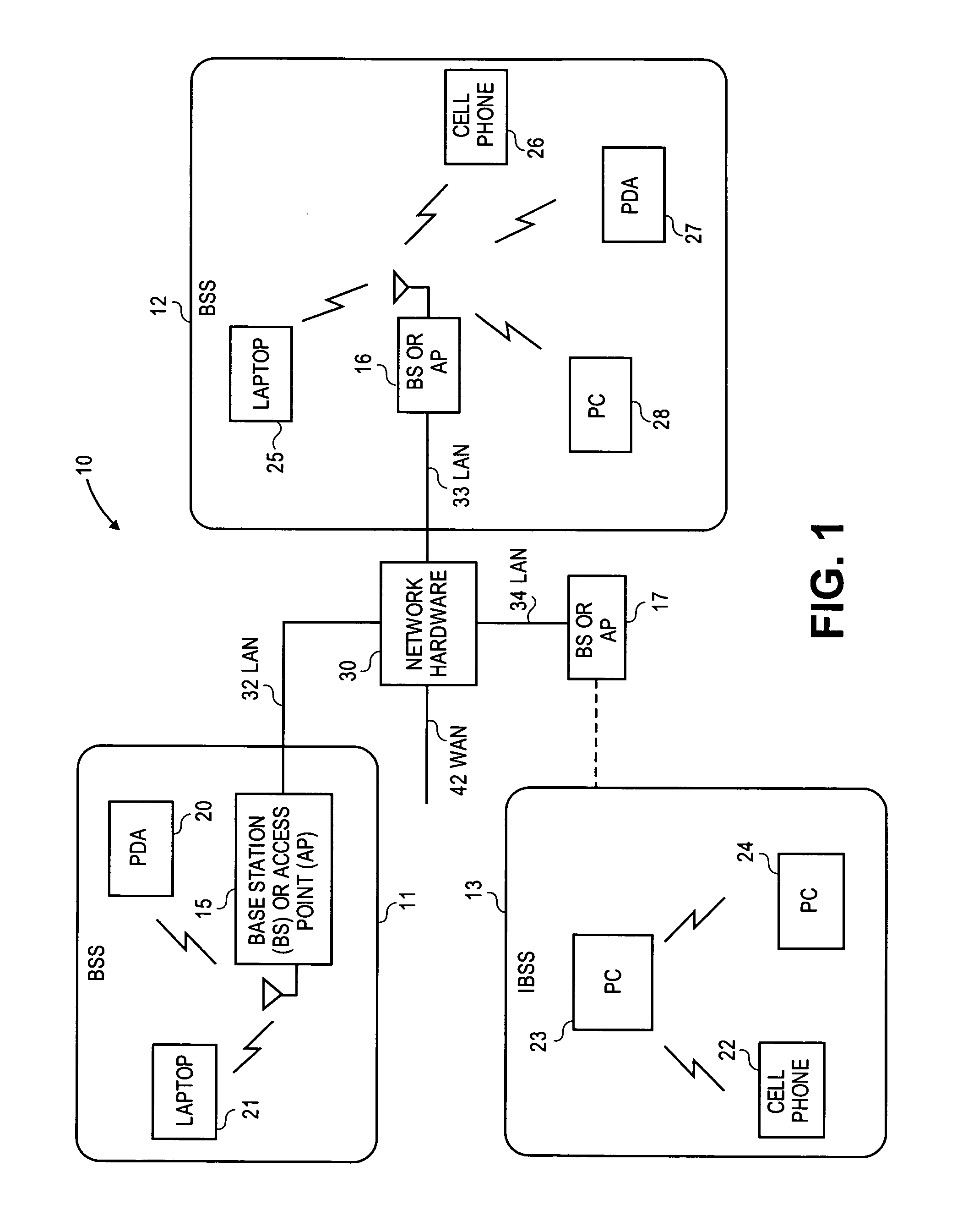
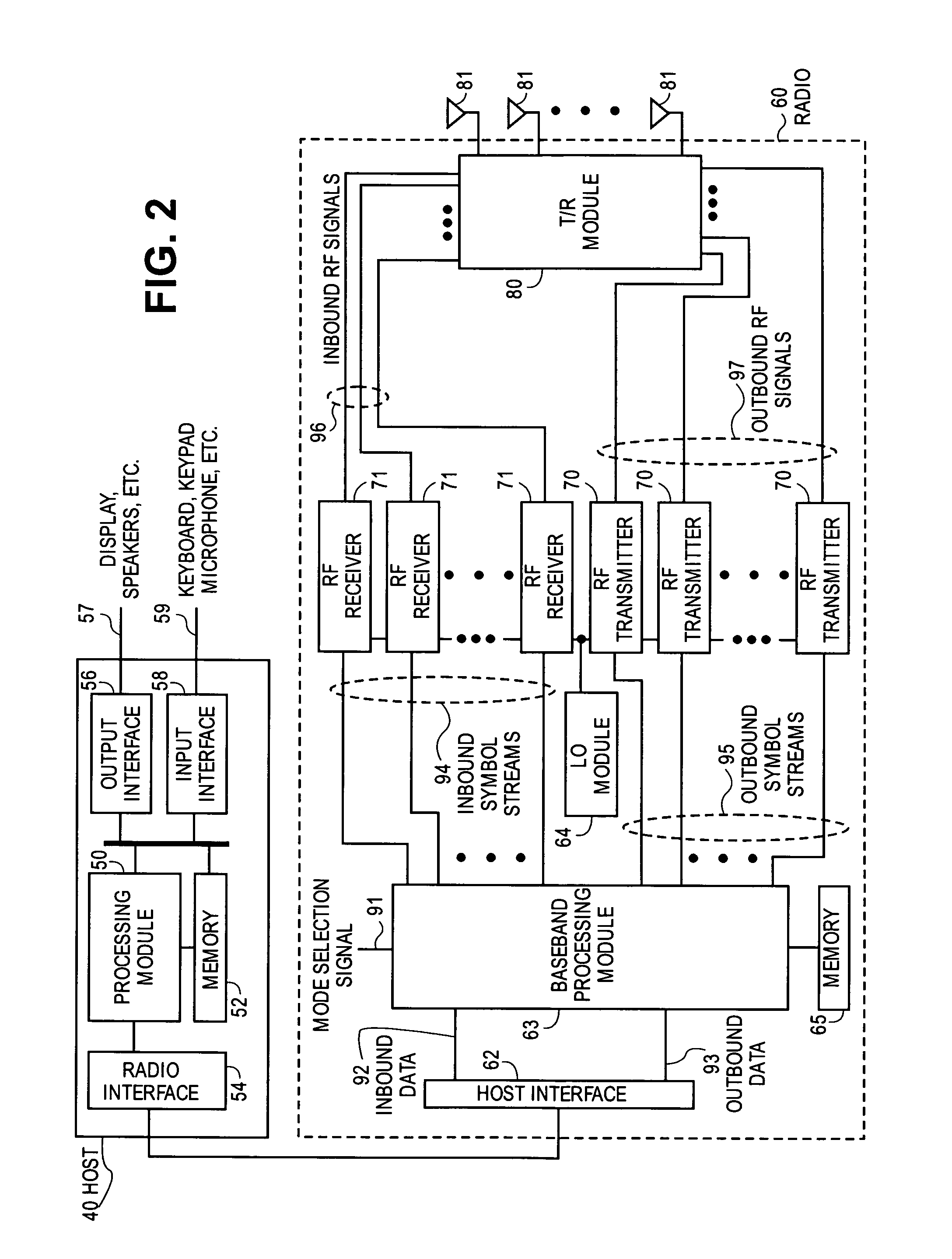
[0024]FIG. 1 is a schematic block diagram illustrating a communication system 10 that includes a plurality of base stations and / or access points (BS / AP) 15, 16, 17, a plurality of wireless communication devices 20-28 and a network hardware component 30. Network hardware component 30, which may be a router, switch, bridge, modem, system controller, et cetera, may provide a wide area network (WAN) coupling 31 for communication system 10. Furthermore, wireless communication devices 20-28 may be of a variety of devices, including laptop computers 21, 25; personal digital assistants (PDA) 20, 27; personal computers (PC) 23, 24, 28; and / or cellular telephones (cell phone) 22, 26. The details of the wireless communication devices shown is described in greater detail with reference to FIG. 2.

[0025]Wireless com...


PUM


Abstract

A technique to estimate phase noise across a multiple-input-multiple-output (MIMO) communication channel, in which phase noise estimation is obtained by solving a matrix equation that has more unknowns than available equations. Once the phase noise estimate is determined, appropriate phase correction is applied to correct for phase noise induced errors in the received signal.

Description

BACKGROUND OF THE INVENTION[0001]1. Technical Field of the Invention[0002]The embodiments of the invention relate to wireless communications and more particularly to phase noise estimation and correction in a receiver of a multiple-input and multiple-output system.[0003]2. Description of Related Art[0004]Communication systems are known to support wireless and wire lined communications between wireless and / or wire lined communication devices. Such communication systems range from national and / or international cellular telephone systems, the Internet and to point-to-point in-home wireless networks. Each type of communication system is constructed, and hence operates, in accordance with one or more communication standards. For instance, wireless communication systems may operate in accordance with one or more standards including, but not limited to, IEEE 802.11, Bluetooth, advanced mobile phone services (AMPS), digital AMPS, global system for mobile communications (GSM), code division ...

Claims


Application Information

Patent Timeline
Patent Type & Authority Applications(United States)
IPC IPC(8): H04L1/02
CPCH04B7/0413H04L1/0631H04L5/0023H04L5/0048H04L25/0204H04L25/0228H04L2025/03426H04L25/03159H04L25/03273H04L25/03292H04L27/2657H04L2025/03414H04L25/0242
Inventor GAIKWAD, ROHIT V.MOORTI, RAJENDRA T.
Owner AVAGO TECH WIRELESS IP SINGAPORE PTE
Why Eureka
Try Eureka