Method of converting liquid ring pumps having sealing liquid vents

a liquid vent and liquid ring technology, applied in the direction of piston pumps, positive displacement liquid engines, machines/engines, etc., can solve the problem of reducing shaft power requirements, and achieve the effect of reducing seal flow

Inactive Publication Date: 2012-03-29
GARDNER DENVER NASH
View PDF3 Cites 5 Cited by
  • Summary
  • Abstract
  • Description
  • Claims
  • Application Information

AI Technical Summary

Benefits of technology

[0017]The retasked and converted pump permits operation with reduced seal flow to the pump because the pump no longer relies on sealing liquid venting to accommodate varying compression ratios. Additionally, the retasking allows the pump to operate with sealing volume flow rates greate...

Problems solved by technology

In return, this also reduc...

Method used


Image

  • Method of converting liquid ring pumps having sealing liquid vents
  • Method of converting liquid ring pumps having sealing liquid vents
  • Method of converting liquid ring pumps having sealing liquid vents

Examples


Embodiment Construction

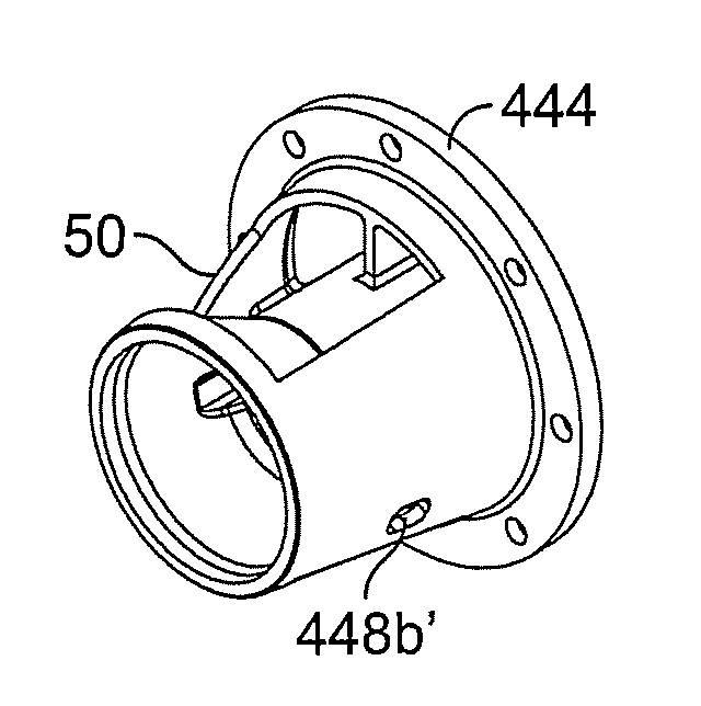
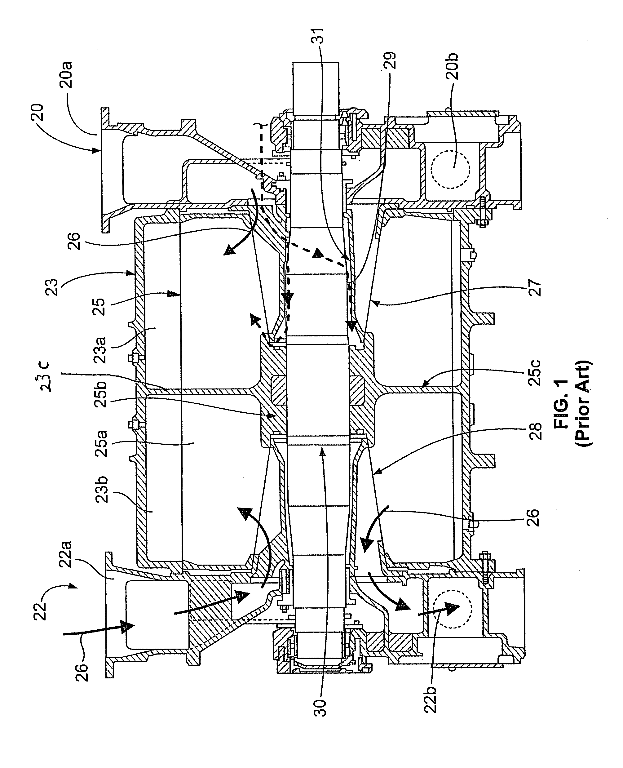
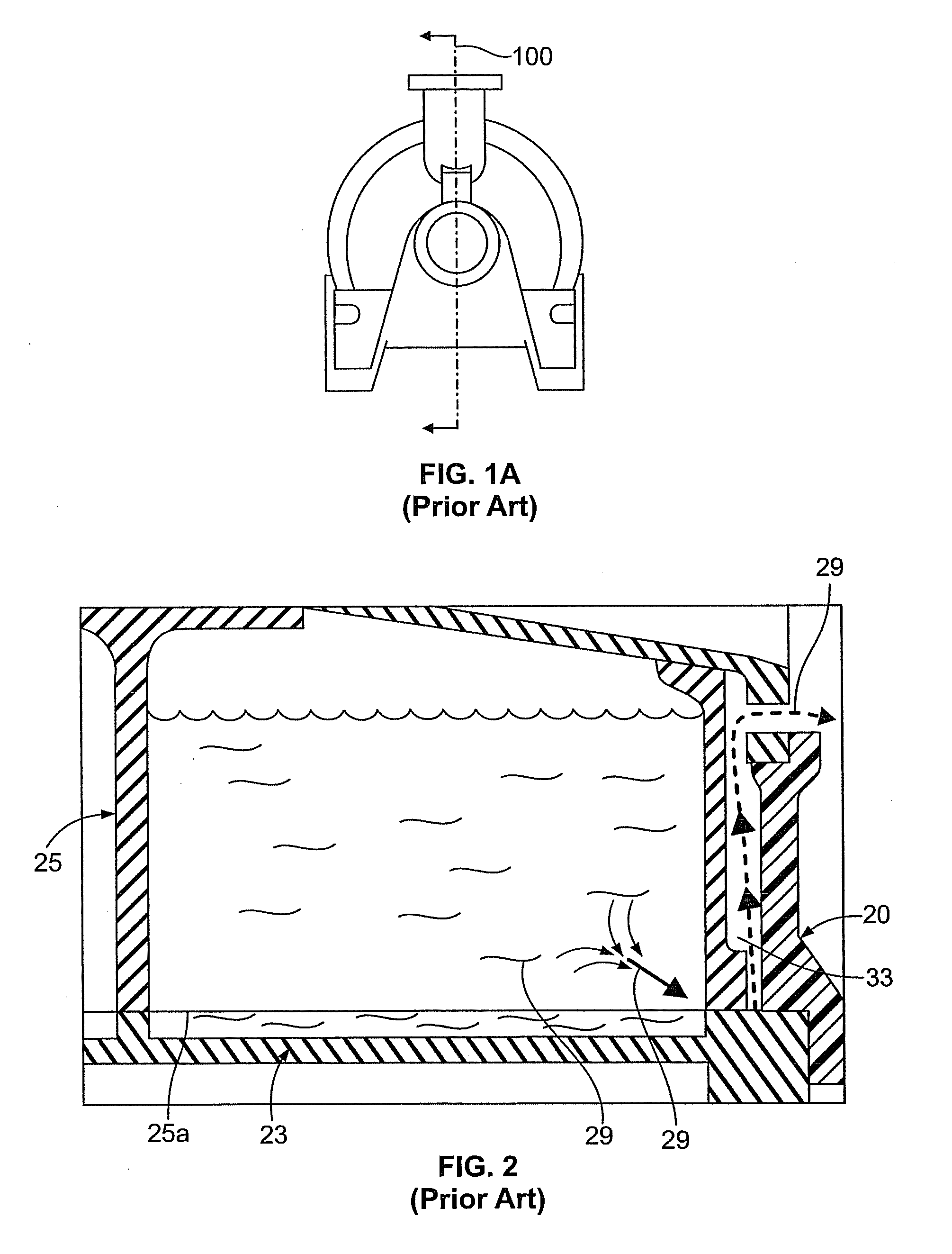
[0029]The present invention converts a pump, which relies on sealing liquid vent paths, also known as liquid leakage paths, into a pump which utilizes a gas vent path. The gas vent path is now used to accommodate varying compression ratios, instead of the sealing liquid vent path. Prior to conversion of the pump, the pump can have all of the features shown in FIGS. 1, 2 and 3. Prior to conversion, FIG. 3 shows a pump head 40 which has a sealing liquid (compressant) vent passage. The vent path or passage is formed by a channel 41a extending through pump head 40 and an aperture 41b extending through a flange 44 of conical member 46. The vent path allows unwanted sealing liquid 29 to exit the working chamber.

[0030]Prior to conversion, the pump head 40 also has a sealing liquid introduction passage. The seal liquid introduction passage is formed by a channel passage 48a extending through pump head 40 and a channel 48b extending through conical member 46.

[0031]To convert the pump shown i...


PUM


Abstract

Converting a liquid ring pump which vents sealing liquid (compressant) from the working chamber of the pump to a liquid ring pump having a gas venting system by retasking a selected passage of the liquid ring pump. The passage is selected from a group of passages consisting of (1) a sealing liquid introduction passage and (2) a sealing liquid vent passage.

Description

FIELD OF INVENTION[0001]The present invention generally relates to a liquid ring pump (“pump”) which vents sealing liquid (compressant) from the working chamber of the pump. More particularly, this invention relates to a method of converting liquid ring pumps using a sealing liquid venting system into a pump having a gas venting system in order to accommodate varying compression ratios.BACKGROUND OF THE INVENTION[0002]Liquid ring pumps are well known. U.S. Pat. No. 4,498,844, Bissell discloses a liquid ring pump with a conical port member. The conical port member has a vent re-circulation port in addition to the conventional intake and discharge ports. U.S. Pat. No. 4,498,844 is incorporated herein in its entirety.[0003]The pump shown in FIG. 1 is of a known configuration of a conical liquid ring pump. FIG. 1 is a vertically oriented sectional view, taken along a plane parallel to the pump's shaft. FIG. 1a shows that the cross-section is taken along line 100. Cross section line 100 ...

Claims


Application Information

Patent Timeline
IPC IPC(8): F04C19/00B23P17/00
CPCF04C19/008Y10T29/49716F04C2230/00F04C2220/20Y10T29/49238F04B7/06F04C19/005
Inventor BISSELL, DOUGLAS ERICBEERS, CHARIES HOWARD
Owner GARDNER DENVER NASH
Why Eureka
Try Eureka