Orthopedic Posture Brace

a technology of orthopaedic braces and stents, applied in the field of orthopaedic braces, to achieve the effects of reducing pain, improving oxygenation, and improving blood flow

Inactive Publication Date: 2012-03-29
AZIMZADEH MAHNAZ
View PDF23 Cites 31 Cited by
  • Summary
  • Abstract
  • Description
  • Claims
  • Application Information

AI Technical Summary

Benefits of technology

[0041](g) a posture promoting device which can be used by anyone over the age of 12.
[0042]These and other advantages of one or more aspects will become apparent from consideration of the ensuing description and accompanying drawings. Although the description above contains many specificities, these should not be construed as limiting the scope of the embodiments but as merely providing illustrations of some of several embodiments. For example, the holster straps may be constructed with magnets in one embodiment and without magnets in another. Magnets have known healing properties and when placed in the

Problems solved by technology

All presently known orthopedic posture braces are unnecessarily large making them difficult or impossible to be worn underneath the user's clothing.
Furthermore, many of these devices tend to unduly restrict or completely prohibit the movement of the user's shoulders making them extremely uncomfortable to wear for more than a short period of time.
These braces are large, cumbersome, and force the user to wear the brace over their clothing.
Some of these devices are comprised of wide straps which constrict movement causing discomfort to the user.
Furthermore, many of these devices contain large constricting chest bands and the rhomboid portion of these devices are seldom adjustable vertically.
The bands that comprise these devices tend to be unnecessarily wide and create bulk when worn.
The end result is an uncomfortable brace which causes tension on the shoulders and strain on other parts of the body.
Finally, many of the presently known orthopedic posture braces lack adjustable arms bands or holster straps that would enable the user to quickly

Method used


Image

  • Orthopedic Posture Brace
  • Orthopedic Posture Brace
  • Orthopedic Posture Brace

Examples


Embodiment Construction

[0055]Illustrative embodiments of the invention are described below. The following explanation provides specific details for a thorough understanding of an enabling description for these embodiments. One skilled in the art will understand that the invention may be practiced without such details. In other instances, well-known structures and functions have not been shown or described in detail to avoid unnecessarily obscuring the description of the embodiments.

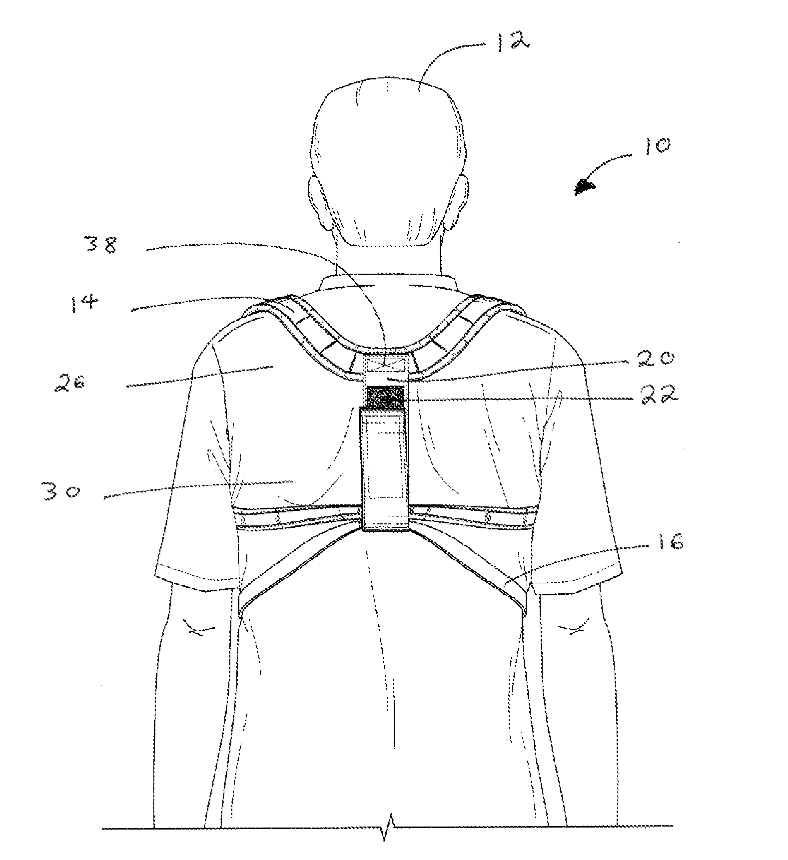
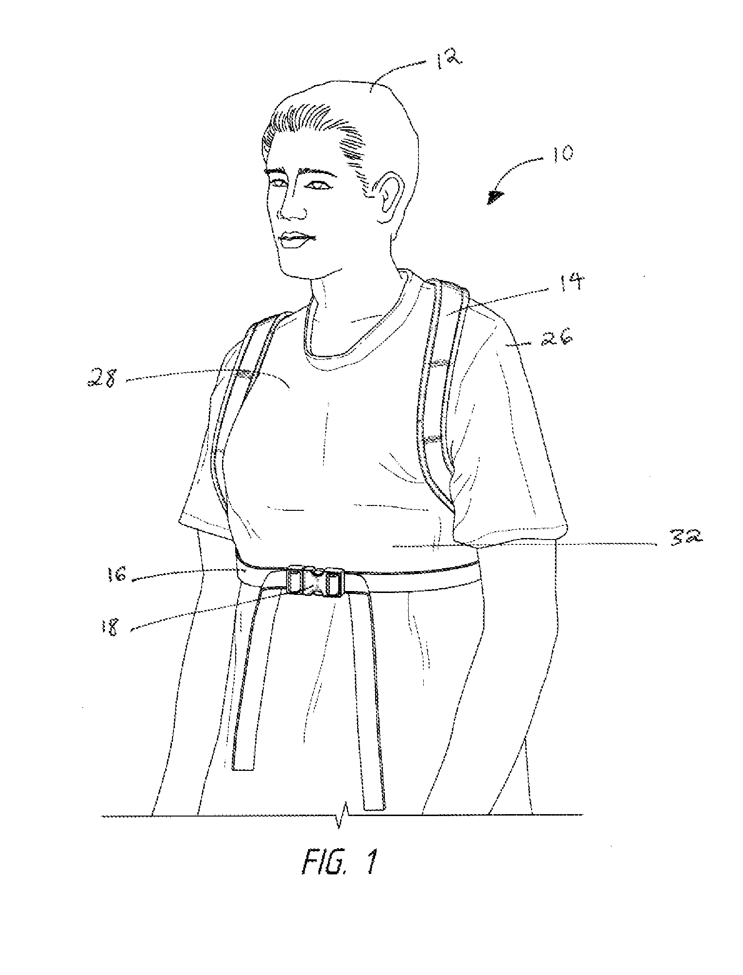
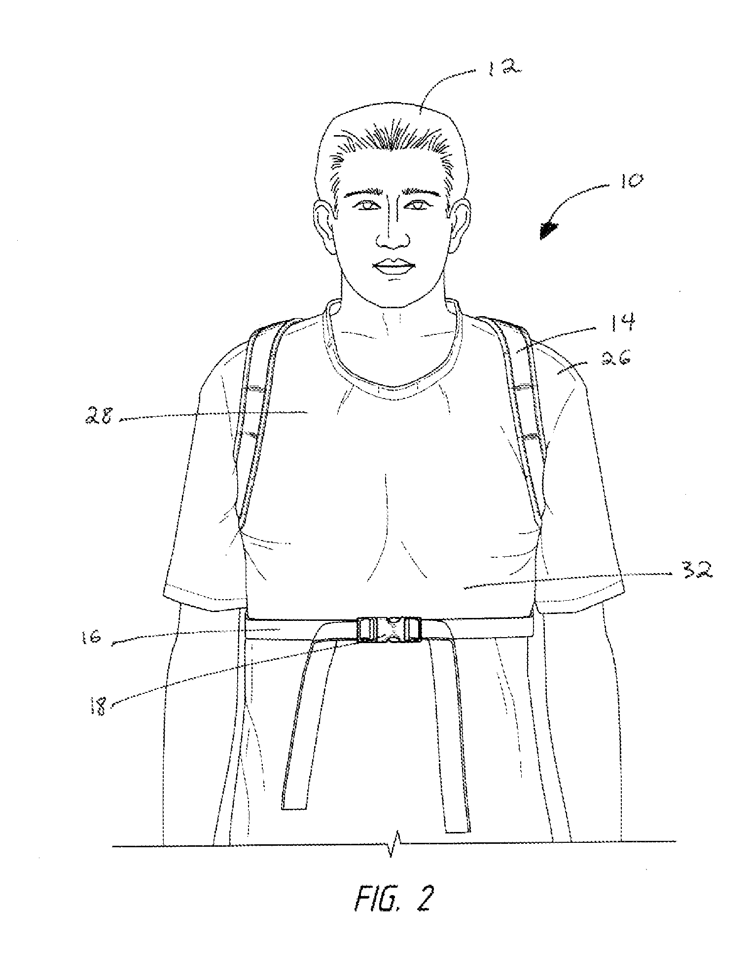
[0056]One embodiment of the orthopedic posture brace 10 is illustrated in FIGS. 5, 6, 7A, 7B, and 8. When worn correctly as illustrated in FIGS. 1, 2, 3A, 3B, and 4, the posture brace 10 will promote proper posture in the user 12.

[0057]The posture brace 10 has two holster straps 14 that, when worn, completely encircle the users shoulders 26. In one embodiment, the holster straps 14 may be padded to provide additional comfort to the user 12. As illustrated in FIG. 3A, the holster straps 14 may be made from it a single piece of m...


PUM

PropertyMeasurementUnit
Heightaaaaaaaaaa
Tensionaaaaaaaaaa

Abstract

One embodiment of an orthopedic posture brace comprising a holster strap that forms two arm loops when attached to an axial strap and two abdominal straps. When worn, the holster straps encircle the user's shoulders. The axial strap will rest against the thoracic region of the user's back. After the two abdominal straps pass through a loop at the bottom of the axial strap, the two ends not connected to the holster strap may be fastened together around the front of the user's abdomen. Tightening the ends of the abdominal strap will cause tension in the holster straps urging the user's shoulders rearward to encourage proper spinal alignment and reduced slouching or hunching over. The amount of tension generated by tightening the abdominal straps will determine how far back toward the spinal column the user's shoulders are pulled.

Description

CROSS-REFERENCE TO RELATED APPLICATIONS[0001]The present application claims priority to U.S. Provisional Patent Application Ser. No. 61 / 385,841 entitled ORTHOPEDIC POSTURE BRACE, filed on Sep. 23, 2010, which is hereby incorporated by reference as to its entirety.BACKGROUND[0002]The following is a tabulation of some prior art that presently appears relevant:U.S. Pat. Nos.Pat. No.Kind CodeIssue DatePatentee  756,237AApr. 5, 1904Hunkins3,116,735AJan. 2, 1964Geimer3,548,818ADec. 22, 1970Kaplan4,080,962AMar. 28, 1978Berkeley6,440,094B1Aug. 27, 2002Maas7,134,969B2Nov. 14, 2006Citron7,901,371B1Mar. 8, 2011YayntraubU.S. Patent Application Publications[0003]Publication NumberKind CodePubl. DateApplicantNone foundForeign Patent Document[0004]None foundNonpatent Literature Documents[0005]None foundNOTICE OF COPYRIGHT AND TRADE DRESS[0006]A portion of the disclosure of this patent document contains material which is subject to copyright protection. This patent document may show and / or describe...

Claims


Application Information

Patent Timeline
IPC IPC(8): A61F5/00B23P11/00
CPCY10T29/49826A61F5/024
Inventor AZIMZADEH, MAHNAZ
Owner AZIMZADEH MAHNAZ
Why Eureka
Try Eureka