
Tip for medical implant delivery system

a technology of medical implants and tips, applied in the field of medical implant delivery systems and methods, can solve problems such as difficulty in getting the valve to the exact right location in the patien

Active Publication Date: 2012-03-29
ST JUDE MEDICAL LLC
View PDF15 Cites 108 Cited by
  • Summary
  • Abstract
  • Description
  • Claims
  • Application Information

AI Technical Summary

Problems solved by technology

Because valves of the type described above are basically implanted by remote control (because the valve is inside the patient at the far end of delivery apparatus that is manipulated and controlled from its proximal end outside the patient), it can be difficult to get the valve to exactly the right location in the patient before releasing it from the delivery apparatus.

Method used


Image

  • Tip for medical implant delivery system
  • Tip for medical implant delivery system
  • Tip for medical implant delivery system

Examples


Embodiment Construction

[0029]Embodiments of the presently disclosed delivery systems are described herein in detail with reference to the drawings, wherein like reference numerals identify similar or identical elements. In the description which follows, the term “proximal” refers to the end of the delivery system, or portion thereof, which is closest to the operator, while the term “distal” refers to the end of the system, or portion thereof, which is farthest from the operator.

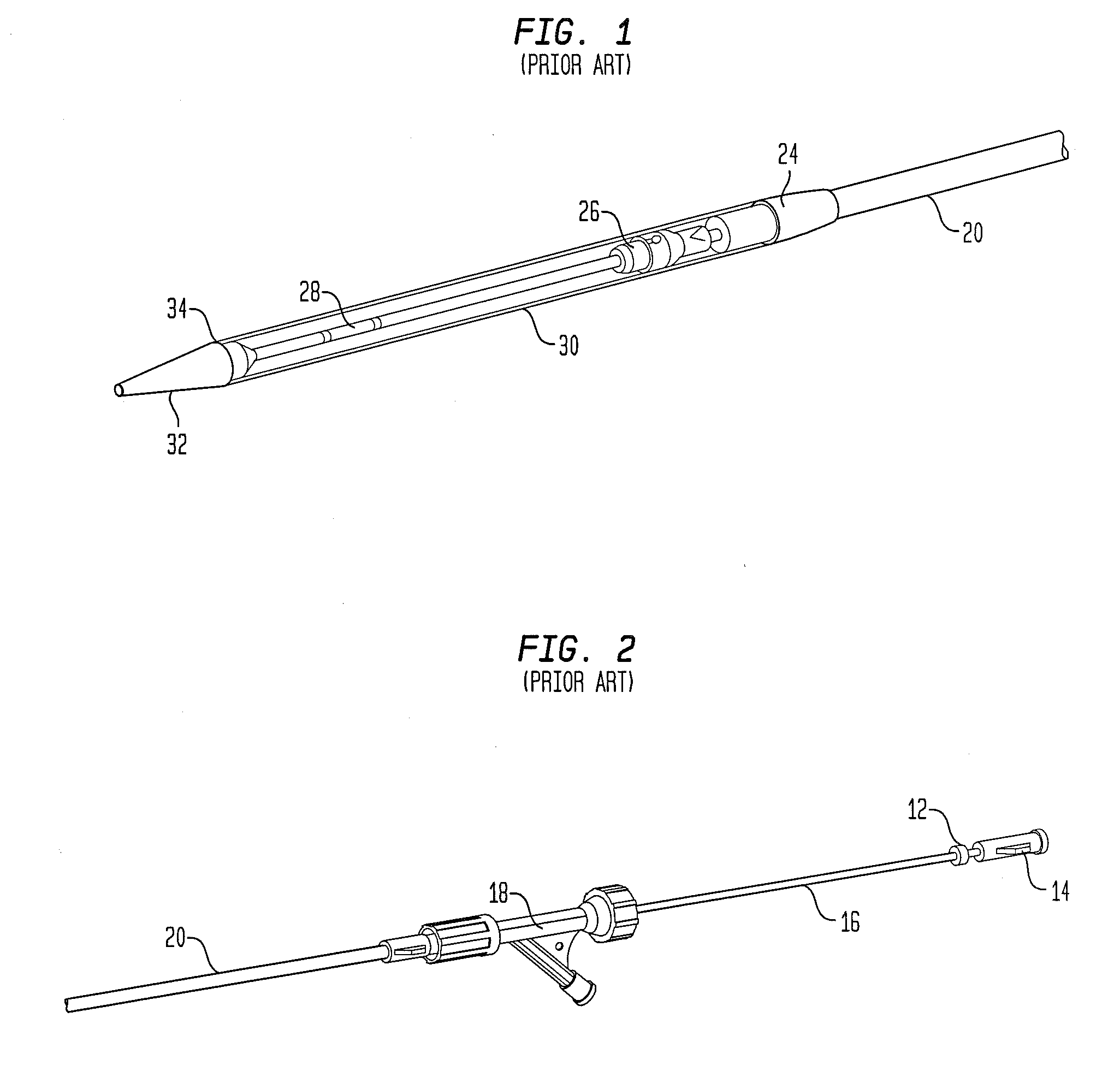
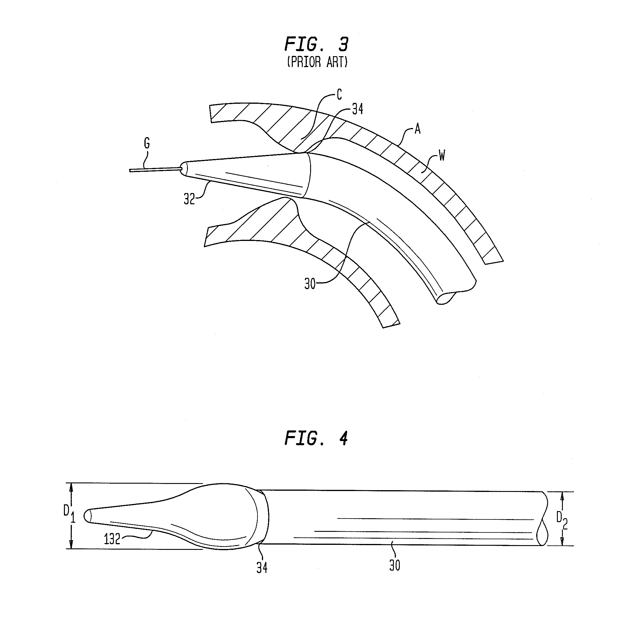
[0030]FIGS. 1 and 2 depict the distal and proximal portions, respectively, of a conventional delivery system for collapsible prosthetic heart valves. The delivery system includes an inner tube 16 having a guidewire lumen extending therethrough. A proximal hub 14 is disposed at the proximal end of the inner tube 16 and is adapted for connection to another system or mechanism, such as a handle, a syringe or other device for displacing the distal sheath 30. Mechanisms for displacing the distal sheath 30 are described in International ...


PUM


Abstract

A delivery system for delivering and deploying a medical implant, such as a prosthetic heart valve, includes an elongated support member, a sheath, and a tip. The sheath is movable relative to the elongated support member between a distal position overlying the medical implant and a proximal position exposing the medical implant for release from the delivery system. The tip is attached to the elongated support member and is positioned at a distal end of the sheath when the sheath is in the distal position. The tip has a compressed condition and an expanded condition, and a maximum diameter in the expanded condition that is larger than the outer diameter of the sheath.

Description

CROSS-REFERENCE TO RELATED APPLICATIONS[0001]The present application claims the benefit of the filing date of U.S. Provisional Application No. 61 / 374,435, filed Aug. 17, 2010, the disclosure of which is hereby incorporated by reference herein.BACKGROUND OF THE INVENTION[0002]The present disclosure relates to medical implant delivery systems and methods and, more particularly, to delivery systems and methods for positioning an expandable prosthetic heart valve in a patient's vasculature.[0003]Prosthetic heart valves are usually implanted in the human heart to replace natural valves. These valves essentially function as check valves, permitting the blood to flow through the valves in a downstream direction, but blocking blood flow in a reverse or upstream direction. Some prosthetic heart valves include an annular valve housing or body with a central orifice and occludes. The orifice provides a passageway for the blood, and the occludes open and close to regulate the passage of blood. ...

Claims


Application Information

Patent Timeline
Patent Type & Authority Applications(United States)
IPC IPC(8): A61B17/00
CPCA61F2/966A61F2/2436A61F2250/0018A61F2250/0019A61F2/2433
Inventor WANG, HUISUNGLAZIER, VALERIE J.
Owner ST JUDE MEDICAL LLC
Learn More