Valve integrating a sensor

a sensor and valve technology, applied in the direction of valve operating means/release devices, mechanical equipment, transportation and packaging, etc., can solve problems such as making the valve fragile, and achieve the effect of increasing the size of the second antenna elemen

Inactive Publication Date: 2012-04-05
SCHREDER SA
View PDF6 Cites 2 Cited by
  • Summary
  • Abstract
  • Description
  • Claims
  • Application Information

AI Technical Summary

Benefits of technology

[0022]In a complementary manner, the valve comprises an electrically conductive tip, on an interior shoulder of which the spring is pressing, said tip being fixed to the body and supplementing the second antenna element. The tip is used for example for the fastening of the valve on another element. It is also used to increase t...

Problems solved by technology

The capsule of this sensor is off-centered in relation to its means of fastening, which ma...

Method used


Image

  • Valve integrating a sensor
  • Valve integrating a sensor
  • Valve integrating a sensor

Examples


Embodiment Construction

)

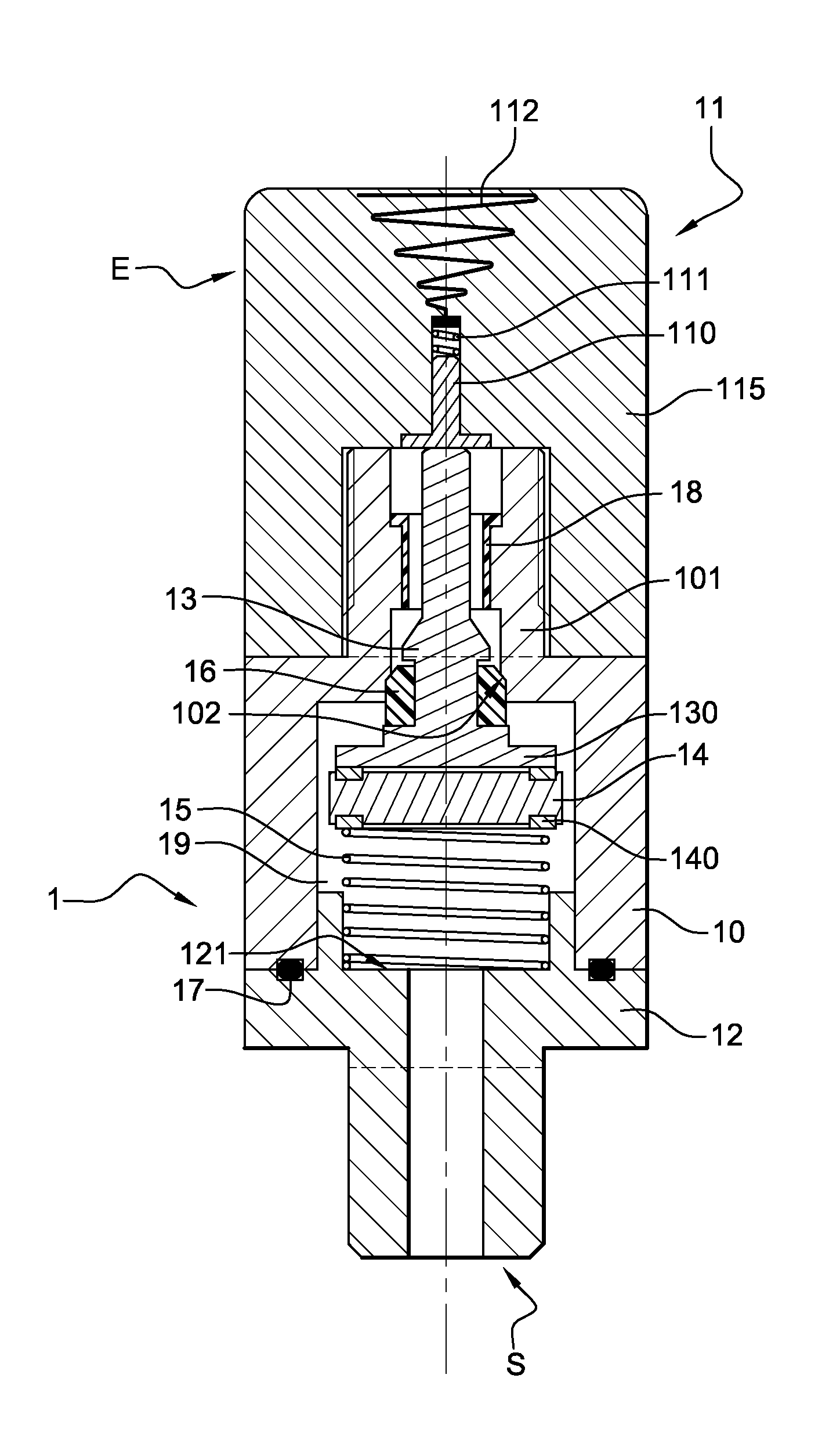
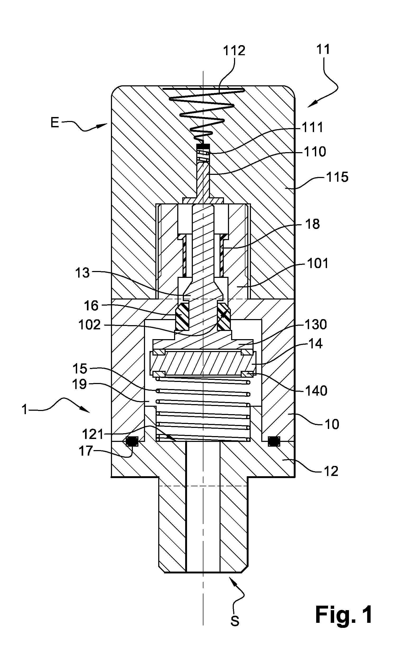
[0027]A valve 1 according to a first embodiment of the invention, shown in FIG. 1, is intended to close off a fluid reservoir, not shown, and to allow for the filling or the draining of the reservoir. The valve 1 comprises an inlet E to which an inflation tube can be connected and an outlet S intended to emerge inside the reservoir. By way of a non-restricted example, this reservoir can be a tire of a vehicle wheel or a membrane expansion vessel intended for heating installations.

[0028]The valve 1 comprises a metal body 10 of a generally tubular shape. On the inlet E side, the body 10 comprises a threaded portion 101 whereon a stopper 11 is screwed in a removable manner. On the outlet S side, a tip 12 is screwed into the body 10 on an internal threading. The tip 12 is also made of metal and a sealing O-ring 17 is inserted between the body 10 and the tip 12. The tip 12 is pierced axially and emerges in a passage chamber 19 delimited in the body 10.

[0029]A rod 13, forming a portion o...


PUM


Abstract

A valve incorporates a sensor which can be remotely interrogated wirelessly. A body of the valve comprises a seat, a mobile assembly comprising a rod forming a plug with the seat, by way of a sealing component for closing off and releasing a fluid passage on command. The sensor is fixed to a base at the lower end of the rod.

Description

BACKGROUND[0001]The invention relates to a valve incorporating a wireless sensor, i.e. which can be remotely interrogated wirelessly, such as a pressure and / or temperature sensor.[0002]A valve making it possible to close off or to open a fluid passage on command such as a gas, air or liquid is known. It comprises for example an assembly mobile in translation in a body, comprised of a rod forming a plug by the intermediary of a sealing component pressing against a seat of the body. When the sealing component is thrust against the seat, the passage is closed off. When the rod is maneuvered, for example via a mechanical press, the passage is opened in order to allow the fluid to pass.[0003]The contact of the sealing component mounted on the rod against the seat is provided for example by the pressure of the fluid itself, possibly assisted by a spring which acts on the rod. The maneuvering of the rod can be controlled manually, by an actuator or by the fluid itself when the pressure of ...

Claims


Application Information

Patent Timeline
IPC IPC(8): F16K31/02H01Q1/44
CPCB60C23/0496B60C23/0408
Inventor GROSLAMBERT, DAVID
Owner SCHREDER SA
Why Eureka
Try Eureka