Cantilever bracket mounted on a seat

a cantilever and seat technology, applied in the field of cantilever brackets, can solve the problems of high production cost, high storage and transportation cost, and high production cost of b>10/b> of different specifications, and achieve the effect of high production, storage and transportation cos

Active Publication Date: 2012-04-05
WANG TENG
View PDF20 Cites 85 Cited by
  • Summary
  • Abstract
  • Description
  • Claims
  • Application Information

AI Technical Summary

Benefits of technology

[0008]In view of the aforementioned drawbacks of the conventional bracket to be mounted on a seat—namely high production, storage, and transportation costs and a fixed configuration that cannot be adjusted, the inventor of the present invention made great effort in research and experiment and finally succeeded in developing a cantilever bracket to be mounted on a seat. It is hoped that the present invention can solve the foregoing problems effectively.

Problems solved by technology

As people's dependence on cars increases, drivers and passengers spend more and more time in cars and become demanding of the comfort and convenience of use of the limited car interior space.
As a result, not only is the convenience of use of the conventional bracket 10 substantially restricted, but also the production of brackets 10 of different sizes increases manufacturers' labor and material costs.
Moreover, brackets 10 of different specifications incur high storage and transportation costs as well as high production costs.
The audio / video playing device 14 may end up too far away from the backseat passenger, or the forward / backward tilt angle or left / right viewing angle of the audio / video playing device 14 may go beyond the passenger's acceptable range, thus making it difficult for the backseat passenger to view the images played by the audio / video playing device 14.
According to the above, the production, storage, and transportation costs of the conventional bracket tend to be high, and the invariable positions of the curved portions of the conventional bracket may hinder the use of the audio / video playing device or other devices installed on the conventional bracket.

Method used


Image

  • Cantilever bracket mounted on a seat
  • Cantilever bracket mounted on a seat
  • Cantilever bracket mounted on a seat

Examples


Embodiment Construction

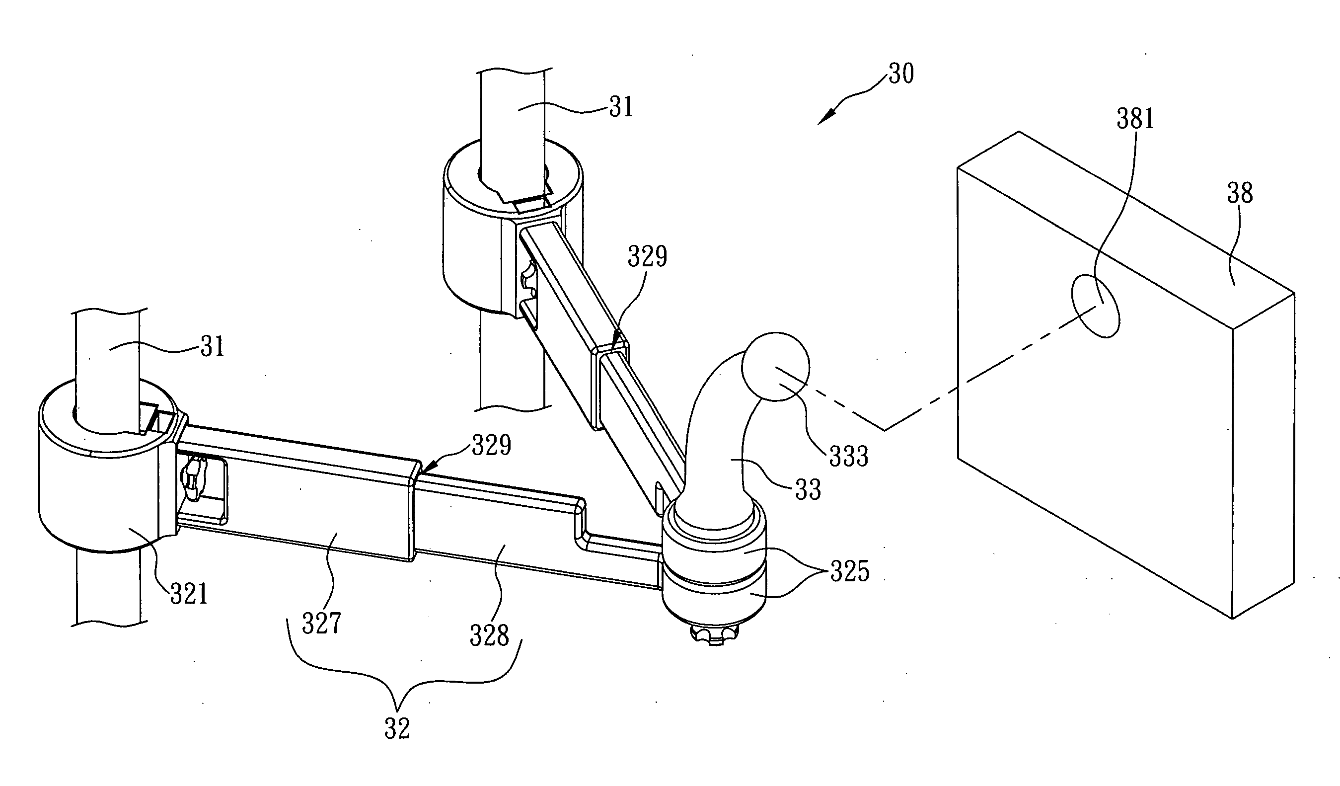
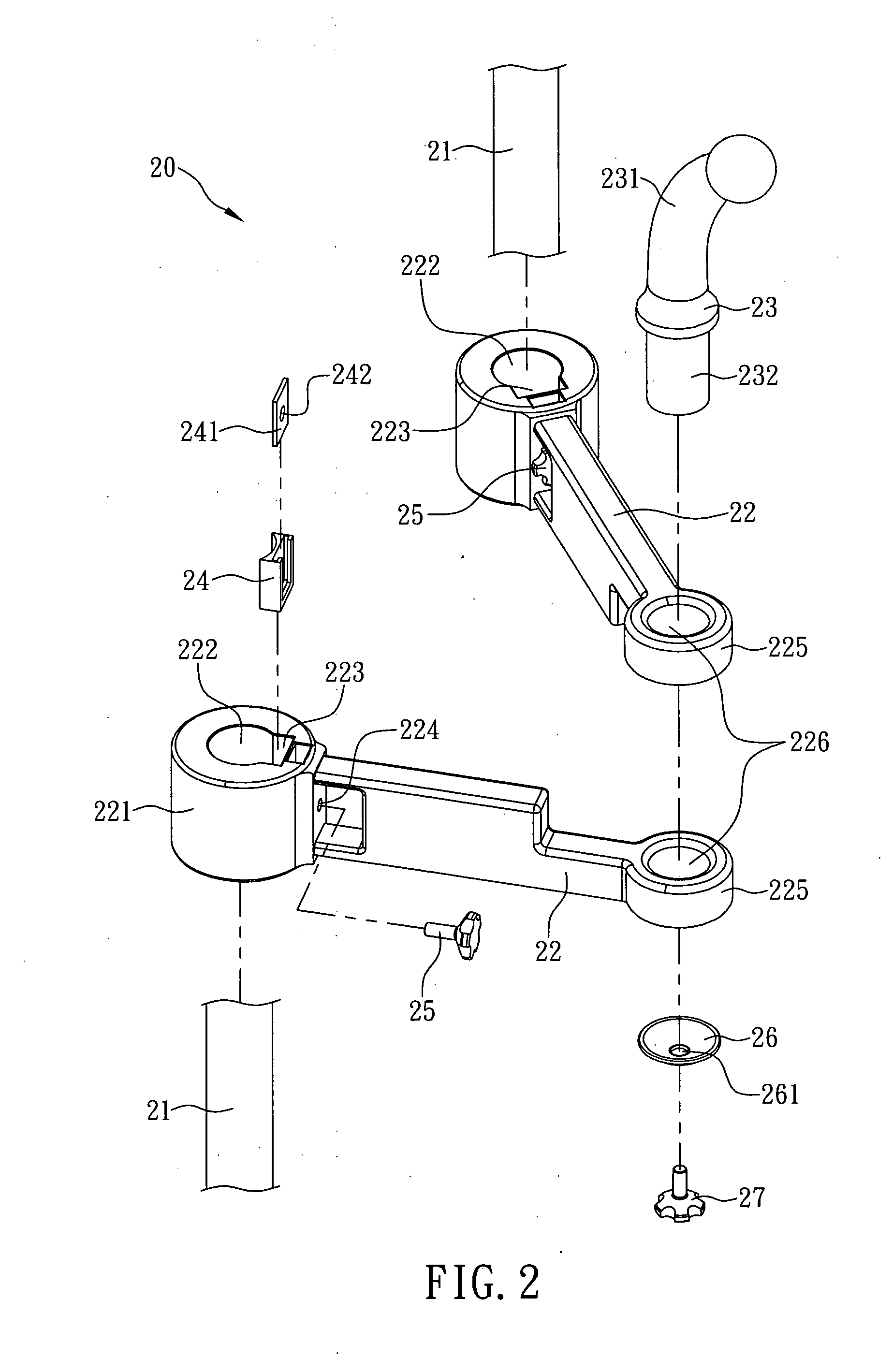
[0017]The present invention provides a cantilever bracket to be mounted on a seat. Referring to FIG. 2 for the first preferred embodiment of the present invention, a cantilever bracket 20 is configured to be secured to two headrest supporting rods 21 of a seat and includes two cantilevers 22 and a post 23. A fixing seat 221 is provided at one end of each cantilever 22 and is formed with a through channel 222 through which the corresponding rod 21 can pass. Each fixing seat 221 has an inner wall surface concavely provided with a receiving cavity 223. The receiving cavities 223 correspond in position to the through channels 222 respectively and are each configured to receive a buffer block 24. Each fixing seat 221 further has an outer wall surface provided with a through hole 224. The through holes 224 correspond in position to and are in communication with the receiving cavities 223 respectively. Each of two first screws 25 has one end passing through the corresponding through hole 2...


PUM


Abstract

The present invention is to provide a cantilever bracket mounted on two headrest supporting rods of a seat, which includes two cantilevers and a post. The cantilever has one end provided with a fixing seat having a through channel through which the corresponding rod can pass, and the other end provided with a pivot seat. The post having one end provided with a supporting portion for supporting or hanging an object, and the other end provided with a first pivot which passes through pivot holes of the two pivot seats and thereby pivotally connects the two cantilevers as a single unit of which the distance between the two fixing seats is adjustable. As such, the cantilever bracket is applicable to seats of various headrest supporting rods with different spacings therebetween and can eliminate the need to manufacture brackets of different specifications in accordance with the various headrest supporting rod spacings.

Description

FIELD OF THE INVENTION[0001]The present invention relates to a cantilever bracket mounted on two headrest supporting rods of a seat, which includes two cantilevers each having one end provided with a fixing seat having a through channel through which the corresponding rod can pass and the other end provided with a pivot seat, and a post having one end provided with a supporting portion for supporting or hanging an object and the other end provided with a first pivot which passes through pivot holes of the two pivot seats and thereby pivotally connects the two cantilevers as a single unit. As such, the cantilever bracket is applicable to seats of various headrest supporting rods with different spacings therebetween and can eliminate the need to manufacture brackets of different specifications in accordance with the various headrest supporting rod spacings, as is otherwise required in the case of the conventional bracket, the distance between whose two fixing seats is not adjustable.B...

Claims


Application Information

Patent Timeline
Patent Type & Authority Applications(United States)
IPC IPC(8): A47C7/62B60N2/44B60N2/90
CPCB60R11/02B60N2002/4405B60R2011/008B60R2011/0017B60N2002/905
Inventor WANG, TENG
Owner WANG TENG
Why Eureka
Try Eureka