Eureka AIR delivers breakthrough ideas for toughest innovation challenges, trusted by R&D personnel around the world.

Electronic Cigarette Charger

a charger and electronic technology, applied in the direction of electric vehicles, transportation and packaging, tobacco, etc., can solve the problems of polluting the environment, low production efficiency, harm to the human body,

Inactive Publication Date: 2017-08-10
HUIZHOU KIMREE TECH
View PDF13 Cites 39 Cited by
  • Summary
  • Abstract
  • Description
  • Claims
  • Application Information

AI Technical Summary

Benefits of technology

This patent describes an electronic cigarette charger that has several benefits. Firstly, the charger has a suspension structure on the housing, making it easy to carry using ropes, cables, or other items. Secondly, the charger uses elastic metal wires to connect the charging circuit board and other components, making it simple and efficient to assemble. This reduces the risk of false welding and ensures reliable electrical connections. Lastly, the charger is environmentally friendly and safe for human use, as it avoids pollution and harm. Overall, the technical effects of this patent contribute to the improved production efficiency and protection of the user and environment.

Problems solved by technology

Normally, the first electric connecting piece and the second electric connecting piece are respectively connected to the charge circuit board by welding conductive wires, welding operations are relatively inconvenient, thus it results in low production efficiency, and lead in a tin solder is easy to pollute the environment and cause harm to the human body.
Secondly, a false welding is easy to produce when welding, resulting in a unreliable electric connection.
Moreover, a common electronic cigarette charger is not provided with a suspension structure, thus, it is inconvenient to carry when using.

Method used


Image

  • Electronic Cigarette Charger
  • Electronic Cigarette Charger
  • Electronic Cigarette Charger

Examples


Embodiment Construction

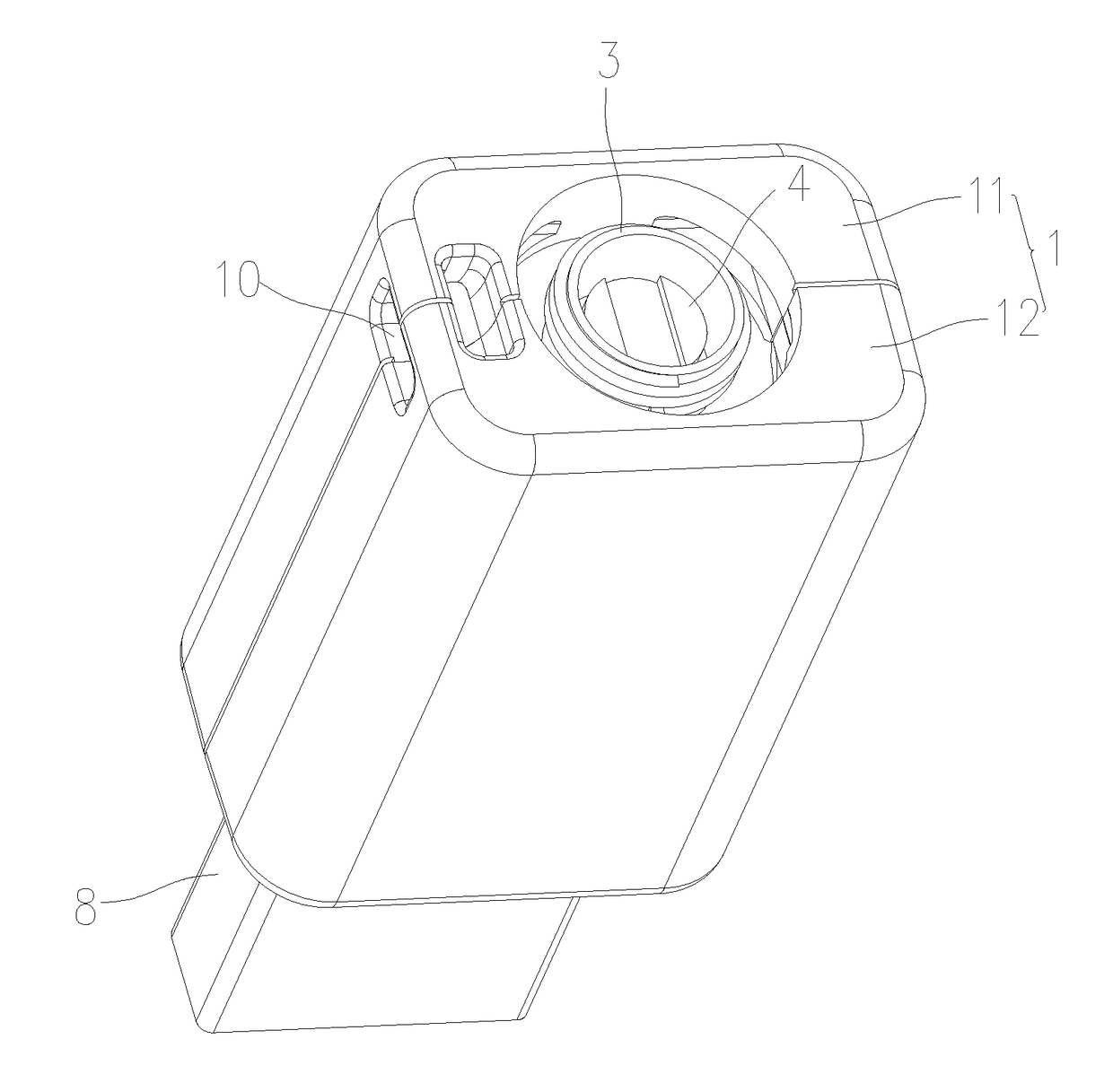
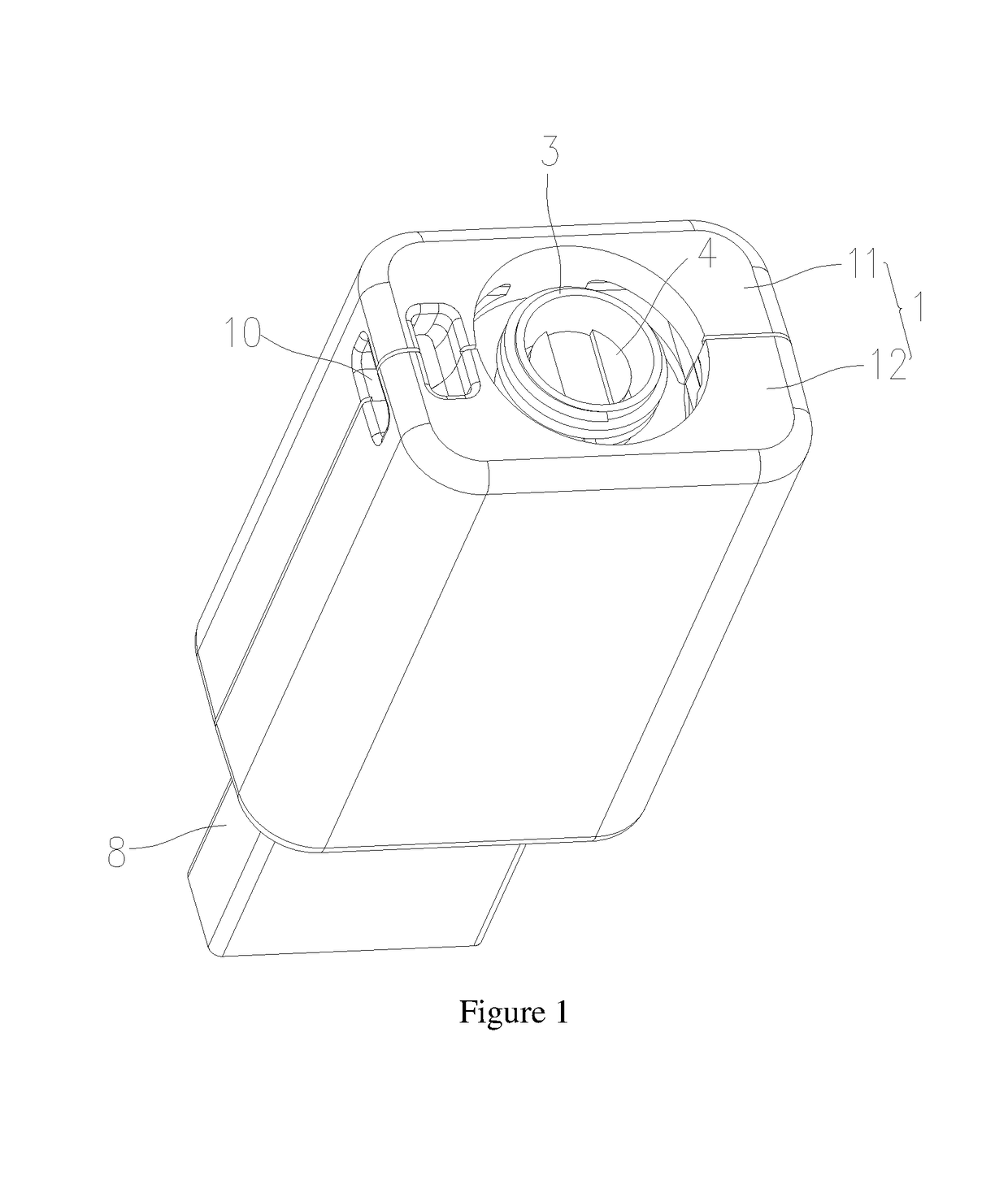
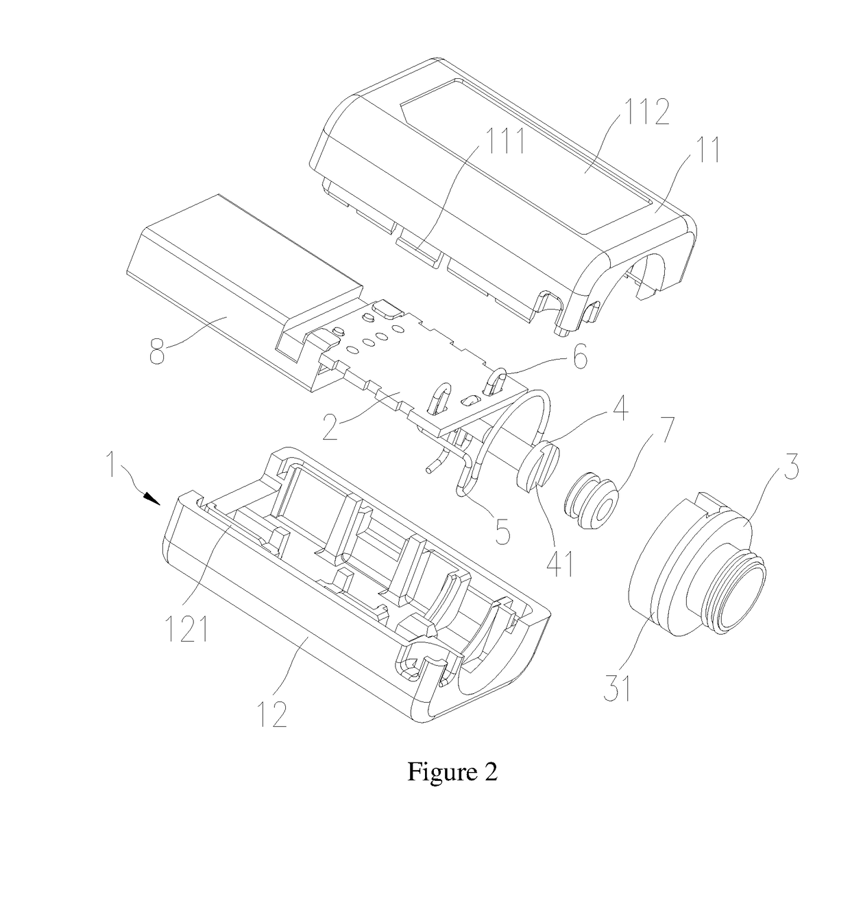
[0037]In order to solve the problems that, in the prior art of an electronic cigarette charger, a first electric connecting piece and a second electric connecting piece are normally connected to the charge circuit board by welding conductive wires, welding operations are inconvenient, thus it results in a low production efficiency, and lead in a tin solder is easy to pollute an environment and cause harm to human body, and commonly the electronic cigarette charger is not provided with a suspension structure, thus, it is inconvenient to carry when using, a main improvement of the present invention is that a suspension structure is arranged on a housing of the electronic cigarette charger. When users need to carry the electronic cigarette charger, a rope, a cable buckle or other items which is passed through the suspension structure can make the electronic cigarette charger attach to the rope, the buckle or other items, thereby facilitating the carrying. Secondly, as structures of tha...


PUM


Abstract

An electronic cigarette charger, comprising a housing, a charging circuit board, a first electric connecting piece and a second electric connecting piece, a first elastic metal wire, a second elastic metal wire, and a suspension structure arranged on the housing and used for suspending the electronic cigarette charger, wherein one end of the first elastic metal wire and the second elastic metal wire is connected to the charging circuit board in an insertion mode, the other end of the first elastic metal wire is connected to the first electric connecting piece in a buckling mode, and the other end of the second elastic metal wire is connected to the second electric connecting piece in a buckling mode. Therefore, the electronic cigarette charger is convenient to carry and to assemble by skillfully connecting the first elastic metal wire and the second elastic metal wire with remaining components, improving a production efficiency.

Description

FIELD OF THE INVENTION[0001]The present application relates to the field of daily electronic products, and more particularly relates to an electronic cigarette charger.BACKGROUND OF THE INVENTION[0002]An electronic cigarette charger is used to charge an electronic cigarette to increase an ability of endurance of the electronic cigarette. In the prior art, the electronic cigarette charger normally comprises a charge circuit board, and a first electric connecting piece and a second electric connecting piece which are connected to the electronic cigarette. Normally, the first electric connecting piece and the second electric connecting piece are respectively connected to the charge circuit board by welding conductive wires, welding operations are relatively inconvenient, thus it results in low production efficiency, and lead in a tin solder is easy to pollute the environment and cause harm to the human body. Secondly, a false welding is easy to produce when welding, resulting in a unre...

Claims


Application Information

Patent Timeline
IPC IPC(8): H02J7/00A24F47/00A24F40/90
CPCH02J7/0044A24F47/00H02J7/0052A24F40/90H02J7/00
Inventor LIU, QIUMING
Owner HUIZHOU KIMREE TECH
Why Eureka
Eureka Blog
Learn More