Apparatus for mounting and inflating a tire and wheel assembly

a technology for inflating and mounting tires and wheels, which is applied in the field of inflator heads, can solve the problems of significant noise and undesirable vibration of motor vehicles, and bead to break, and achieve the effects of rapid inflators, high production tire inflating, and wide application

Inactive Publication Date: 2006-05-16
DURR SYST INC
View PDF33 Cites 43 Cited by
  • Summary
  • Abstract
  • Description
  • Claims
  • Application Information

AI Technical Summary

Benefits of technology

[0013]An advantage of the present invention is to provide an improved design of an apparatus for mounting and inflating a tire and wheel assembly that is compact and has a wide application range from an individually owned tire shop, a private garage, or the like.
[0014]Another advantage of the present invention is to provide an apparatus capable of accommodating a wide variety of wheel and tire sizes without modifying the inflator assembly.
[0015]Still another advantage of the present invention is to provide high production tire inflating and mounting apparatus capable of rapidly inflating a tire and wheel assembly supported on inner and outer concentric members or seals, which are operably connected and supported by a carriage mechanism movably from an isolated position to and away from a tool or mating device after the tire and wheel assembly is mounted and inflated.
[0016]Still another advantage of the present invention is to provide an improved design of a tire inflating and mounting apparatus that is not complex and bulky in design and integrates inner and outer concentric members with a carriage mechanism thereby reducing number of parts.

Problems solved by technology

It is well known that a non-uniform, i.e. improperly mounted and inflated tire and wheel assembly contributes significantly to noise and vibration of the motor vehicle.
A tire and wheel assembly that is not properly mounted and inflated results in what is commonly referred to as smooth road shake, resulting in the undesirable vibration of the motor vehicle.
If beads of the tire are not properly seated on seats of the wheel, air pressure over, for example 25 psi, may cause the bead to break and the tire and wheel assembly to explode during operation.
The tire inflating station does not teach a tool cooperable with the tire inflating station for mounting the tire about the wheel for inflating the tire and wheel assembly.
The tire and wheel assembly mounting apparatus does not teach a tire inflator assembly having inner and outer concentric members or seals.
Hence practicable, the prior art designs are too complex, non-compact and fit only to be installed and used within established environment of a production line to lubricate and mount the tires within their respective wheels to undergo further inflation.
The application of some of the aforementioned designs is limited mass production and may not be used in individually owned tire shops, located in a private garage, and the like, or at the facility with a limited space.
Other designs may require service that is complicated leading to entire disassembly of the device or apparatus to replace or service parts, such as, for example inner or outer concentric seals.

Method used


Image

  • Apparatus for mounting and inflating a tire and wheel assembly
  • Apparatus for mounting and inflating a tire and wheel assembly
  • Apparatus for mounting and inflating a tire and wheel assembly

Examples


Embodiment Construction

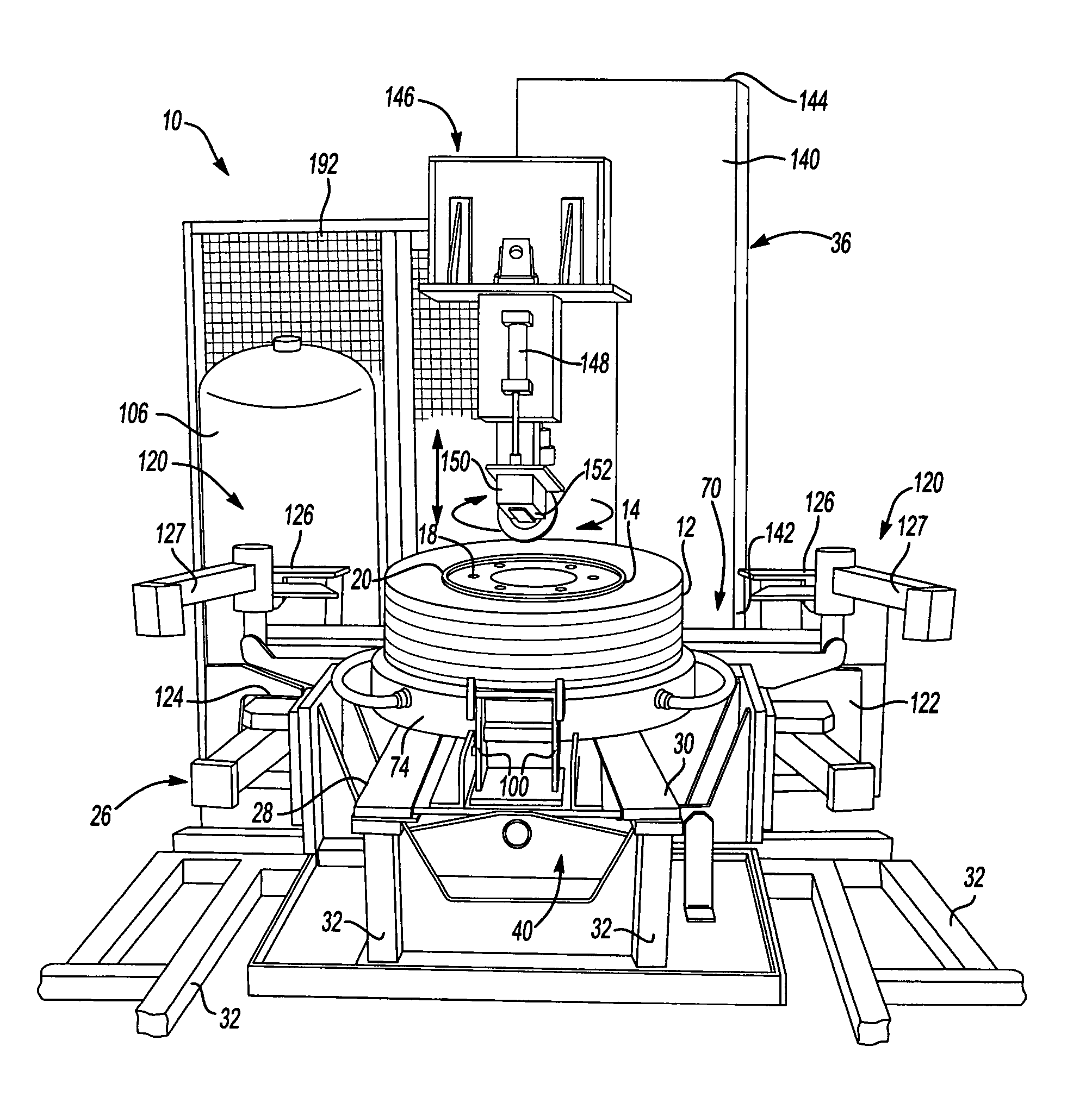
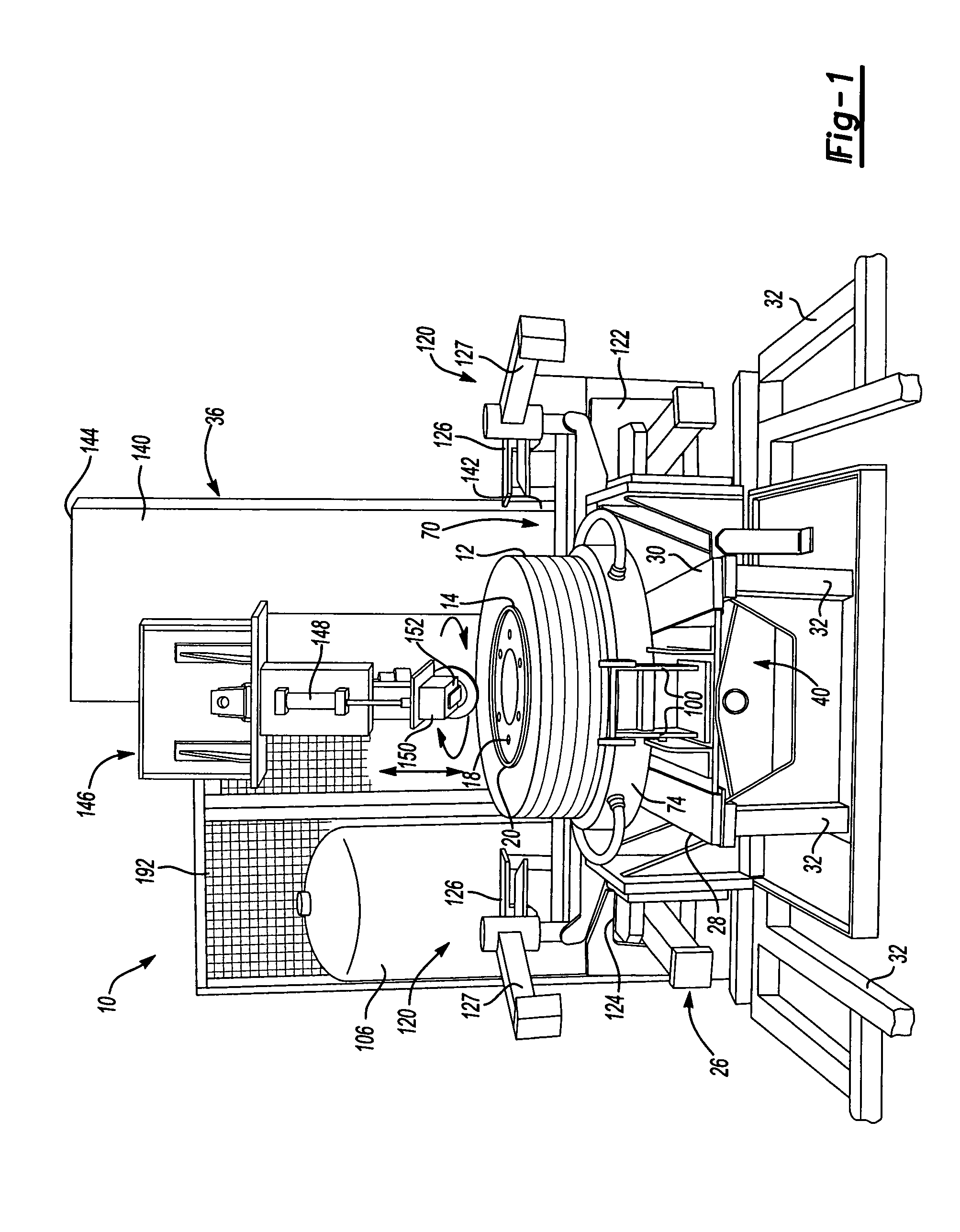
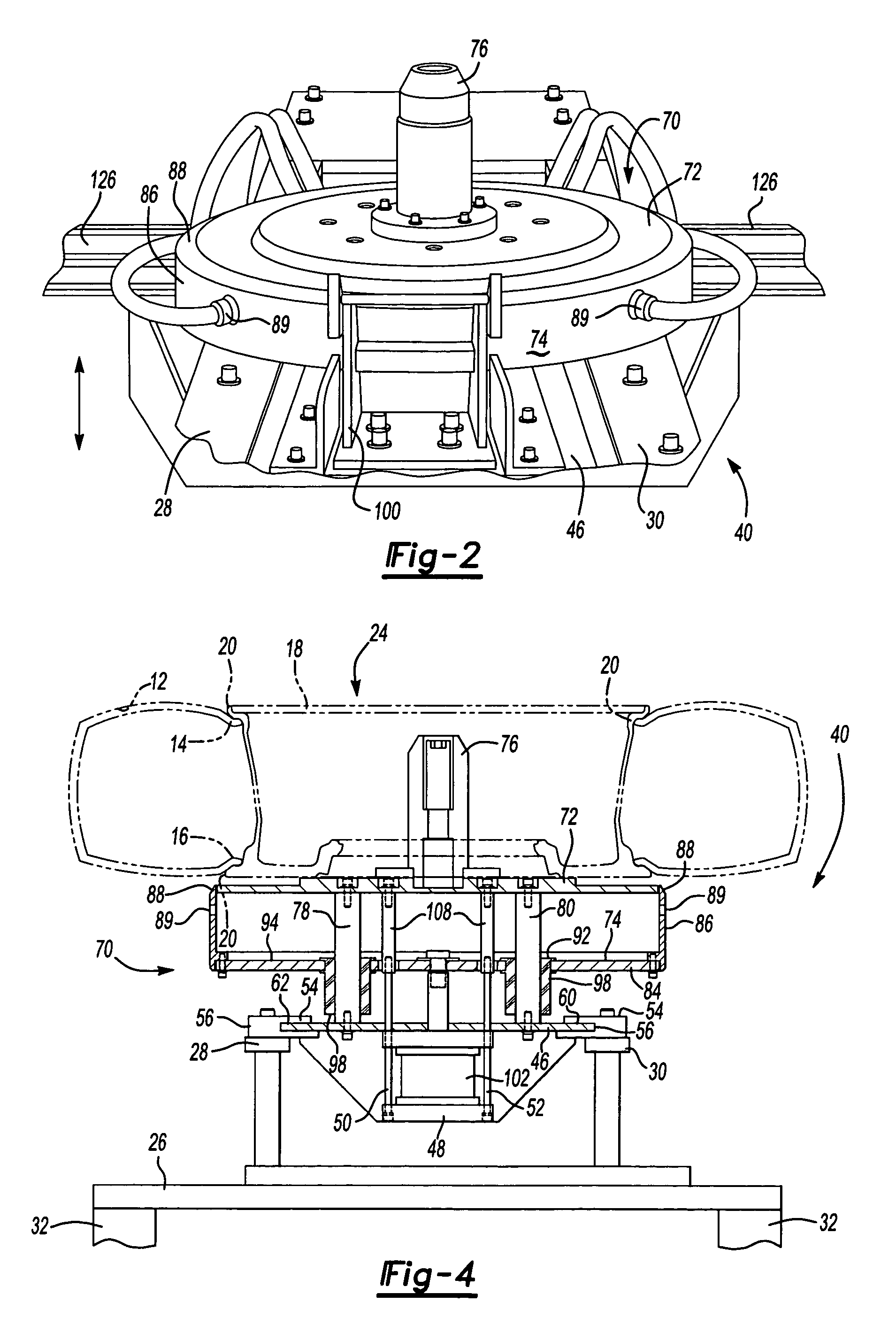
[0025]Referring to the FIG. 1, wherein like numerals indicate like or corresponding parts, an apparatus of the present invention is generally shown at 10. The apparatus 10 is designed for assembling a tire 12 having a pair of beads 14, 16 on a wheel 18 having a pair of seats 20, 22 by forcing the beads 14, 16 of the tire 12 between the seats 20, 22 of the wheel 18. The apparatus 10 includes a work surface defined by a frame, generally shown at 26, which has opposite side walls 28, 30 and a plurality of supports 32, as best shown in FIG. 4, extending downwardly from the frame 26 to a floor 34. A tool or robotic apparatus, generally shown at 36 in FIG. 1, is adjacently positioned by the frame 26, and will be discussed in greater detail, as the description of the present invention proceeds.

[0026]The carriage mechanism 40 is designed for moving the tire and the wheel assembly 24 from an isolated position 42 (FIG. 6) where, for example, an operator 44 is positioned, to the tool 36 and re...


PUM


Abstract

An apparatus (10) of the present invention is designed for assembling and inflating a tire (12) mounted on a wheel (18). A tool (36) of the apparatus (10) rotates around the tire (12) for forcing one of the beads of the tire (12) between the seats of the wheel (18). Inner (72) and outer (74) concentric members are operably connected relative to one another for inflating the tire (12) mounted about the wheel (18). An activator (102) is connected to the outer concentric member (74) for moving the outer concentric member (74) telescopingly relative to the inner concentric member (72) to form a fluid passage (104). A carriage mechanism (40) is connected,to the inner (72) and outer (74) concentric members for reversibly moving the same between an isolated position (42) and the tool (36).

Description

RELATED APPLICATION[0001]The subject patent application claims priority to and all the benefits of U.S. Provisional Patent Application Ser. No. 60 / 477,882 filed on Jun. 12, 2003.FIELD OF THE INVENTION[0002]The subject invention relates to an apparatus for inflating and mounting a tire and wheel assembly, and more particularly to an inflator head having at least two concentric bells selectively moveable with respect to one another to inflate the tire.BACKGROUND OF THE INVENTION[0003]Motor vehicles are commonly supported by pneumatic tires supported on respective wheels, i.e. a tire and wheel assembly. The tire and wheel assembly is among the most important parts of the motor vehicle. Everything concerned with driving, such as moving and stopping of the motor vehicle, involves the tire and wheel assembly. It is well known that a non-uniform, i.e. improperly mounted and inflated tire and wheel assembly contributes significantly to noise and vibration of the motor vehicle. A tire and wh...

Claims


Application Information

Patent Timeline
Patent Type & Authority Patents(United States)
IPC IPC(8): B60C25/132B60C25/138
CPCB60C25/138
Inventor PELLERIN, DANSINKE, CHAD A.HOY, BRIAN
Owner DURR SYST INC
Why Eureka
Try Eureka