Image photographing device having function for compensating for hand vibration

a photographing device and hand vibration technology, applied in the field of hand vibration compensation, can solve the problems of deteriorating compensation performance, image quality deterioration, and inability to obtain sharp photographs

Active Publication Date: 2012-04-05
SAMSUNG ELECTRO MECHANICS CO LTD
View PDF8 Cites 89 Cited by
  • Summary
  • Abstract
  • Description
  • Claims
  • Application Information

AI Technical Summary

Benefits of technology

[0013]An object of the present invention is to provide an image photographing device having a function for compensating for hand vibration in which a driving coil in an X axis direction and a driving coil in a Y axis direction are additionally disposed outside a bobbin having a lens unit mounted therein to simultaneously move, in X and Y axis directions, the bobbin vertically moved through a driving coil in a Z axis direction, thereby simultaneously performing auto focusing and hand vibration compensation.

Problems solved by technology

Accordingly, the receiving sensitivity of the light photographed by the image sensor becomes sensitive, and the image photographed by the image sensor becomes out of focus even with small hand vibration when operating a shutter of the camera or the mobile device, such that image quality is deteriorated.
Therefore, it is impossible to obtain a sharp photograph.
When the lens is moved along the two-axis guide, a compensation performance may be deteriorated due to the friction between the two-axis guide and the lens.
Also, when driving the two-axis guide and the lens or the two-axis guide, noise or foreign material may occur due to the friction with other components.
In addition, since the two-axis guide supports the periphery of the lens, the size of the camera module cannot but be enlarged by a space in which the two-axis guide is mounted.

Method used


Image

  • Image photographing device having function for compensating for hand vibration
  • Image photographing device having function for compensating for hand vibration
  • Image photographing device having function for compensating for hand vibration

Examples


Embodiment Construction

[0031]The acting effects and technical configuration with respect to the objects of an image photographing device having a function for compensating for hand vibration according to an exemplary embodiment of the present invention will be clearly understood by the following description in which exemplary embodiments of the present invention are described with reference to the accompanying drawings.

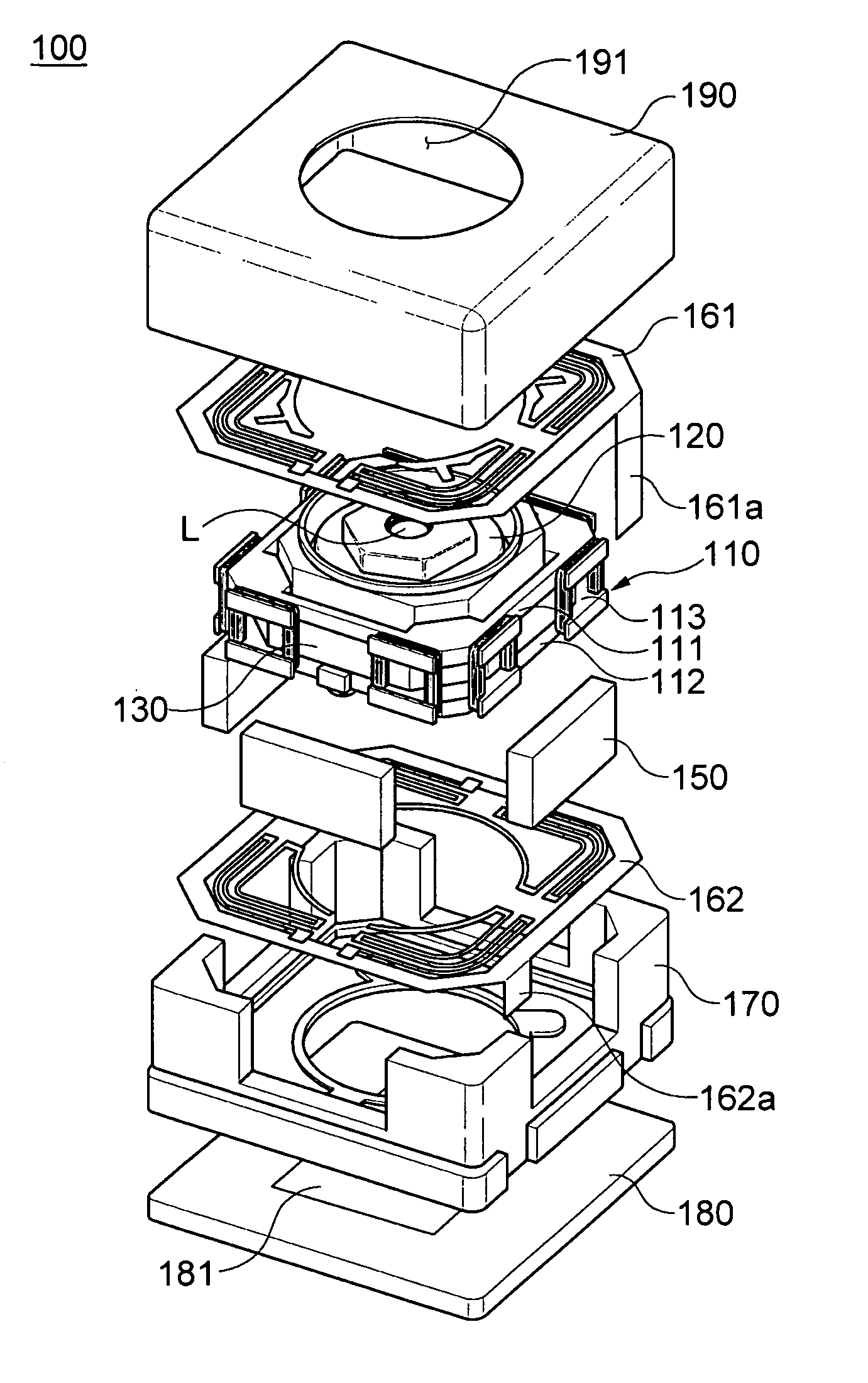
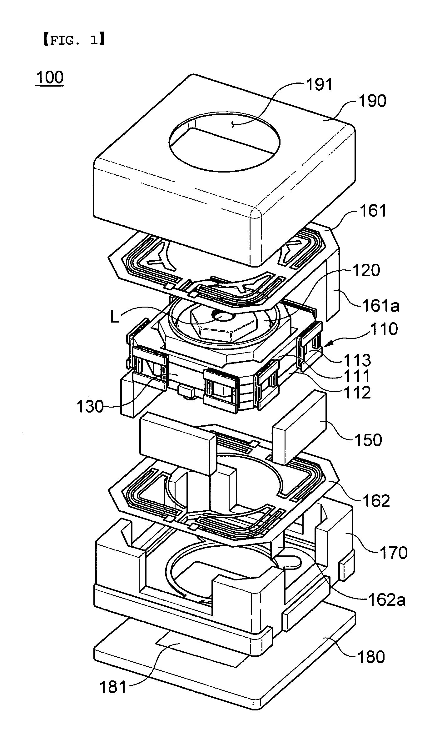
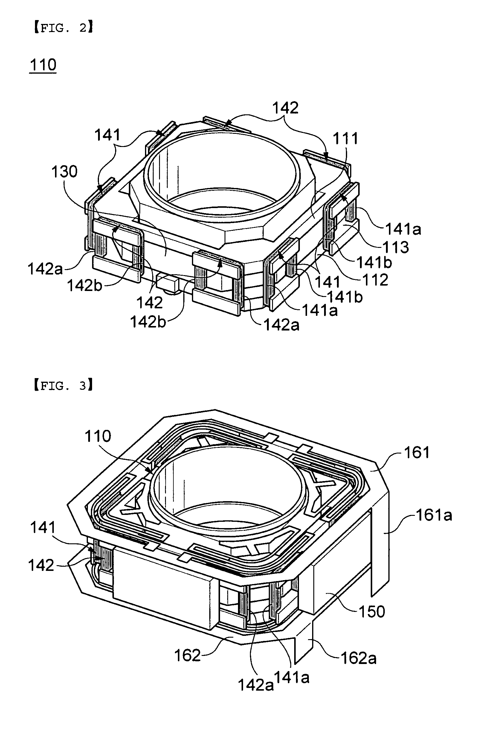
[0032]FIG. 1 is an exploded perspective view of an image photographing device according to an exemplary embodiment of the present invention, FIG. 2 is a perspective view of a bobbin used in the image photographing device according to the exemplary embodiment of the present invention, and FIG. 3 is a perspective view of a state in which elastic members and magnets are mounted on the bobbin used in the image photographing device according to the exemplary embodiment of the present invention.

[0033]As shown in FIGS. 1 to 3, an image photographing device 100 having a function for compensating fo...


PUM


Abstract

Disclosed herein is an image photographing device having a function for compensating hand vibration to simultaneously perform auto focusing and hand vibration compensation. The image photographing device having a function for compensating hand vibration includes: a bobbin having a lens unit mounted therein, a driving coil in a Z axis direction wound on an outer peripheral surface thereof, and a driving coil in an X axis direction and a driving coil in a Y axis direction mounted outside the driving coil in a Z direction; a plurality of magnets mounted outside the driving coil in an X axis direction and the driving coil in a Y axis direction; an elastic member elastically combined with an upper portion and a lower portion of the bobbin; a housing into which the bobbin combined with the magnet and the elastic member is inserted; and a shield case combined with an upper portion of the housing.

Description

CROSS REFERENCES TO RELATED APPLICATION[0001]This application claims the benefit under 35 U.S.C. Section 119 of Korean Patent Application Serial No. 10-2010-0096373, entitled “Image Photographing Device Having Function for Compensating for Hand Vibration”, filed on Oct. 4, 2010, which is hereby incorporated by reference in its entirety into this application.BACKGROUND OF THE INVENTION[0002]1. Technical Field[0003]The present invention relates to an image photographing device having a function for compensating for hand vibration, and more particularly, to an image photographing device having a function for compensating for hand vibration in which coils and magnets are additionally disposed outside a bobbin having a lens unit mounted therein to simultaneously perform auto focusing and hand vibration compensation.[0004]2. Description of the Related Art[0005]Recently, the use of a subminiature camera has gradually increased in a mobile device such as a cellular phone, a notebook, a tabl...

Claims


Application Information

Patent Timeline
Patent Type & Authority Applications(United States)
IPC IPC(8): G03B17/00
CPCG02B27/646H04N5/23287H04N5/2254H04N5/2253H04N23/54H04N23/55H04N23/687
Inventor KWON, OH BYOUNGKIM, SUNG HOONOH, SANG HWAN
Owner SAMSUNG ELECTRO MECHANICS CO LTD
Why Eureka
Try Eureka