
Down hole well tool with expansion tool

Active Publication Date: 2012-04-19
REELWELL AS
View PDF21 Cites 1 Cited by
  • Summary
  • Abstract
  • Description
  • Claims
  • Application Information

AI Technical Summary

Benefits of technology

[0010]Based on this a need has evoked to produce a solution wherein the forces necessary to carry out casing / liner expansion may be reduced.
[0011]In accordance with the inventive down hole well tool, using separate expansion modules, at least two expansion modules, for the expansion of the casing / liner reduces the need for high forces to acquire the necessary expansion. By using at least two expansion modules, the expansion to be carried out is distributed among the expansion modules, and thus the force necessary to cause the deformation of each expansion module is reduced correspondingly, thereby avoiding exposing the system to high level forces.
[0013]The piston(s) may be arranged above and or below the expansion modules or are included in the expansion modules at any position within the extension of the expansion modules in the axial direction of the expansion module. The piston(s) may be provided with means for controlling the communication of fluid between adjacent annulus spaces. In one embodiment the piston may be arranged below the expansion modules, thereby applying a pulling force to the expansion modules. By pulling the expansion modules the inside pressure of the pipe to be expanded will help the expansion process by reducing the required differential pressure across the piston(s).

Problems solved by technology

The forces required for expansion may in some case reach a level wherein the forces may harm the system itself.

Method used


Image

  • Down hole well tool with expansion tool
  • Down hole well tool with expansion tool
  • Down hole well tool with expansion tool

Examples


Embodiment Construction

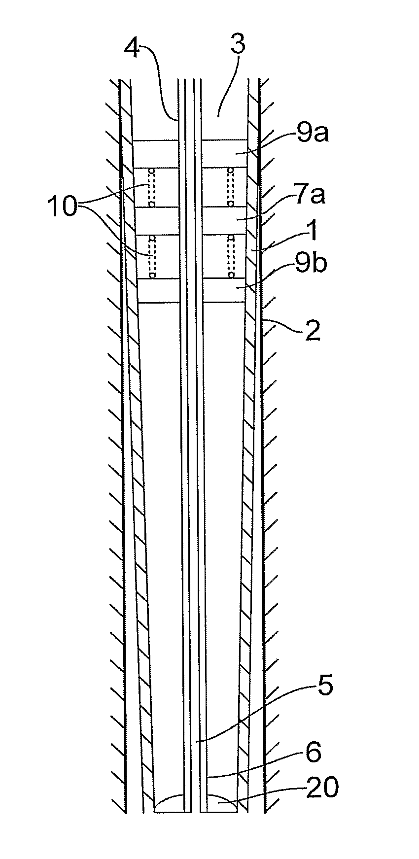
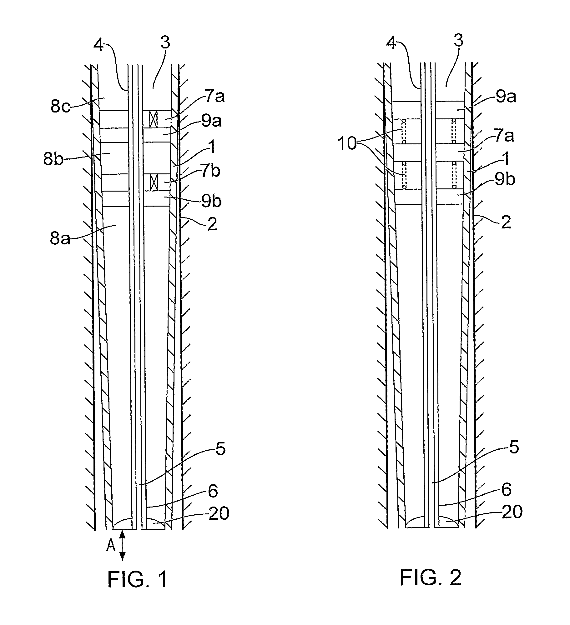
[0030]FIG. 1 shows an embodiment of a down hole well tool 3 for the expansion of a casing / liner 1 in a well bore 2. The down hole well tool 3 comprises a tool unit 4 which is made up by at least one first fluid conduit 6 and a return fluid conduit 5 arranged inside the first fluid conduit 6. When placing the tool unit 4 in the casing / liner to be set in the well bore 2 an annulus appear between the tool unit 4 and the casing / liner 1.

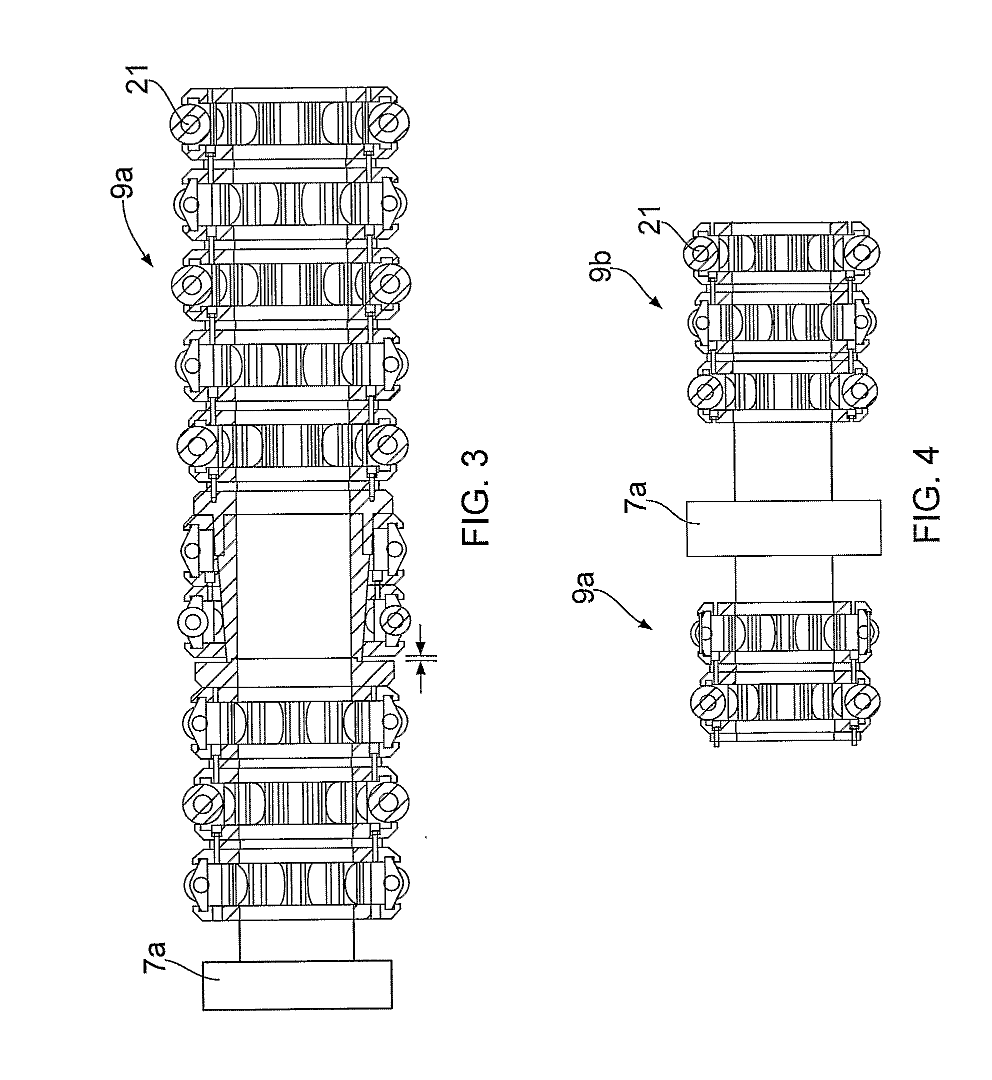
[0031]In the shown embodiment the two pistons 7a, 7b are arranged in the annulus in between the tool unit 4 and the casing / liner 1 dividing the annulus into annulus spaces 8a, 8b , 8c. The features of the pistons 7a, 7b ensure that the two annulus spaces are isolated from each other, to prevent accidental fluid entry in between the annulus spaces, for instance by providing adequate sealing means in between the various parts of the tool unit 4. The two pistons 7a, 7b are each arranged to operate an expansion module 9a, 9b for displacing the expansion modul...


PUM


Abstract

A down hole well tool (3) for installing a casing / liner (1) in a well bore (2), wherein the down hole well tool comprises a tool unit comprising at least one first fluid conduit (6) and a return fluid conduit (5) in use forming an annulus between the tool unit and the casing / liner. The tool unit further comprises at least one piston (7a, 7b) in the annulus dividing the annulus into annulus spaces (8a, 8b, 8c). At least two expansion modules (9a, 9b) for the expansion of the casing are positioned displaced in the axial direction of the casing. The expansion modules are arranged to be moved relative to each other in the axial direction of the casing.

Description

BACKGROUND[0001]1. Field of the Invention[0002]The invention relates to a down hole tool for installing a casing or liner in a well bore.[0003]2. Related Art[0004]U.S. Patent Application No. 2007 / 0169943 (“Vestavik”) discloses a method for setting a casing in a borehole using a running tool including a drilling tool, an expandable casing, an expansion tool, and a packer arranged to seal against the wall of the borehole.SUMMARY[0005]The invention concerns a down hole well tool for installing a casing or a liner in a well bore. The down hole well tool comprises a tool unit comprising at least one first fluid conduit and a return fluid conduit in use forming a well annulus between the tool unit and a well bore, and at least one piston dividing the well annulus into well annulus spaces.[0006]The return fluid conduit may be arranged in the first fluid conduit, leaving an annular space in between the first fluid conduit for the flow of a first fluid, wherein the return fluid may be arrang...

Claims


Application Information

Patent Timeline
IPC IPC(8): E21B23/00E21B23/02
CPCE21B43/105
Inventor VESTAVIK, OLASYSE, HARALD
Owner REELWELL AS
Features
  • Generate Ideas
  • Intellectual Property
  • Life Sciences
  • Materials
  • Tech Scout
  • Unparalleled Data Quality
  • Higher Quality Content
  • 60% Fewer Hallucinations
Learn More