Lighting device, display device and television receiver

Inactive Publication Date: 2012-04-19
SHARP KK
View PDF10 Cites 14 Cited by
  • Summary
  • Abstract
  • Description
  • Claims
  • Application Information

AI Technical Summary

Benefits of technology

[0011]With this configuration, the board reflection member that overlaps with the light source board on the opening side is provided in addition to the chassis reflection member arranged along the inner surface of the chassis. Therefore, for example, even when a hole is formed in the chassis reflection member, apart of the board reflec

Problems solved by technology

As a result, deformation in the boar

Method used


Image

  • Lighting device, display device and television receiver
  • Lighting device, display device and television receiver
  • Lighting device, display device and television receiver

Examples


Example

[0046]A first embodiment of the present invention will be described with reference to FIGS. 1 to 18. In this embodiment, a liquid crystal display device 10 is used as an example. A part of each figure shows an X-axis, a Y-axis and a Z-axis, and a direction of each axis is represented in each figure. It is given that an upper side in FIGS. 4 and 5 is a front side and a lower side in these figures is a back side.

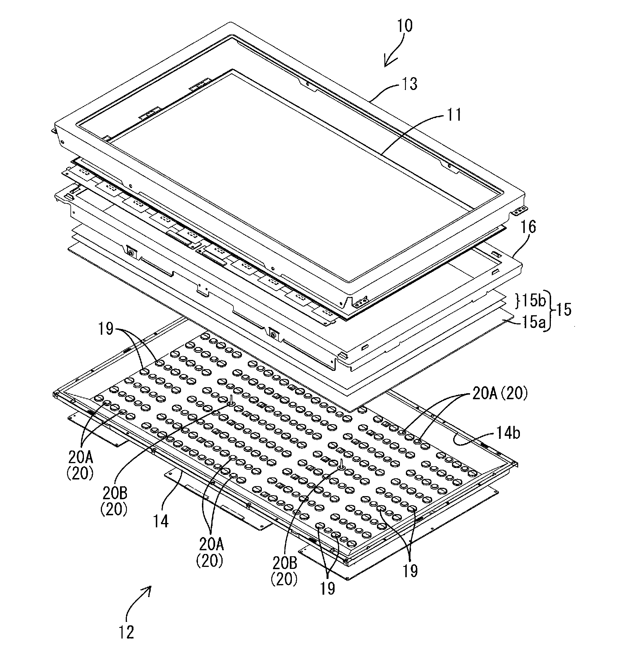
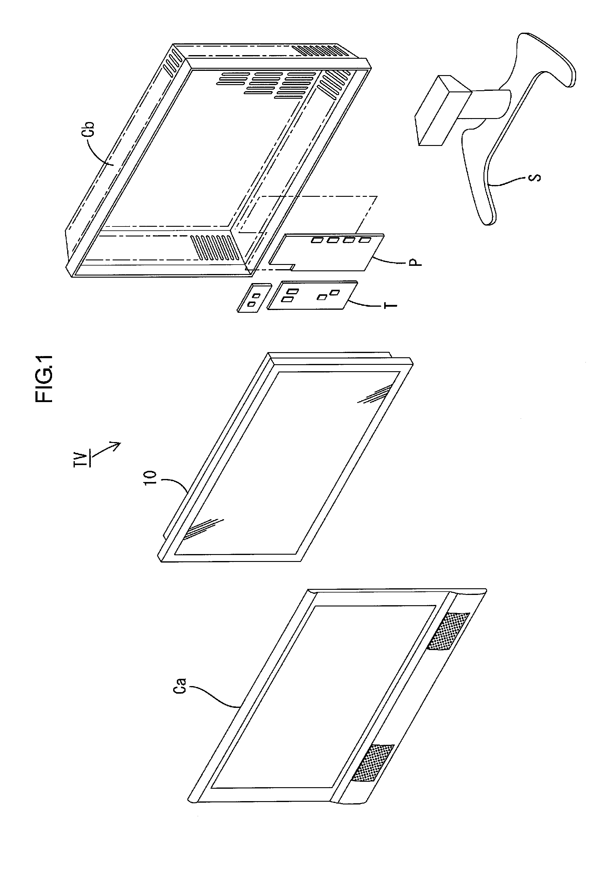
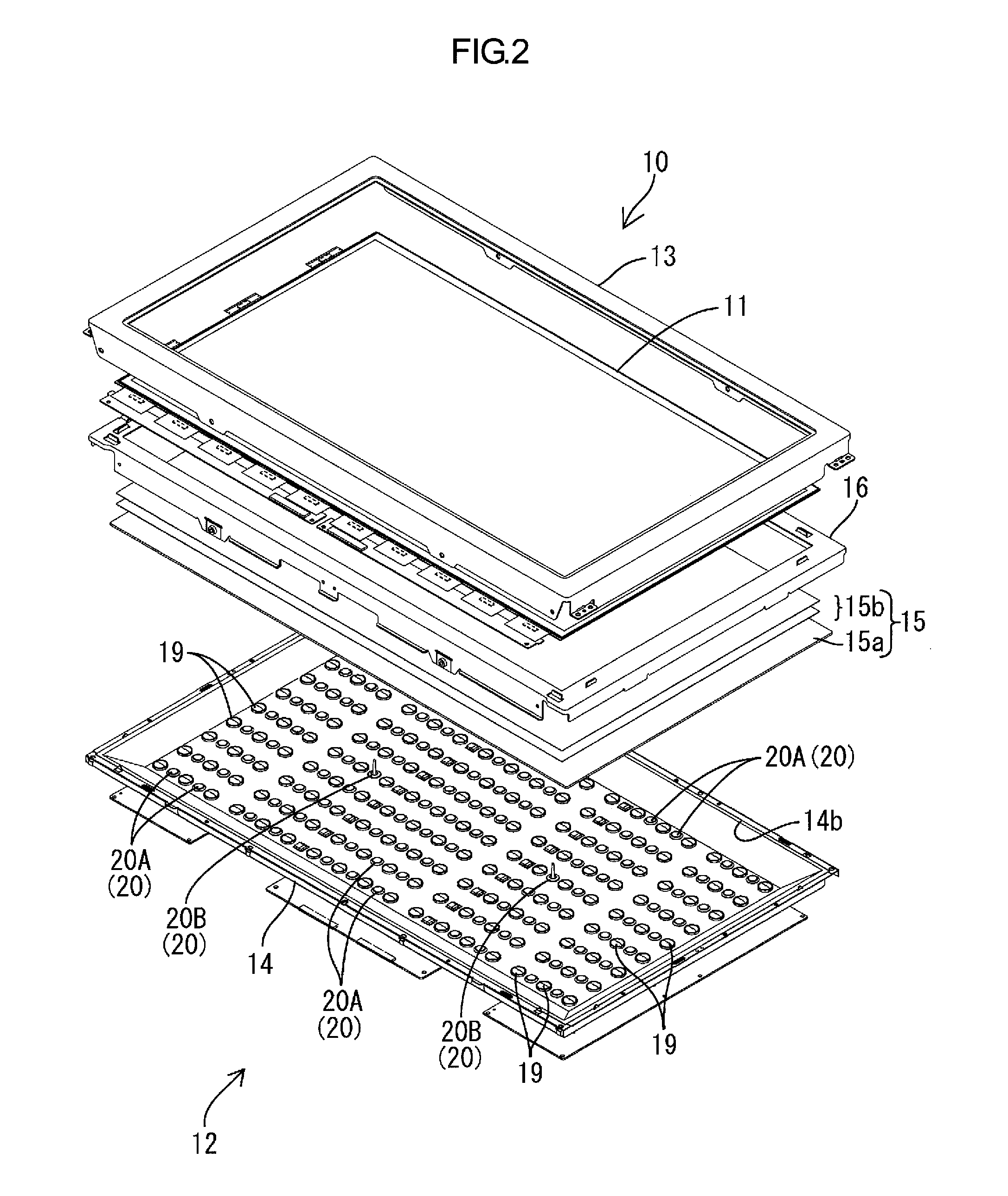
[0047]A television receiver TV according to this embodiment includes, as shown in FIG. 1, the liquid crystal display device 10, front and back cabinets Ca and Cb that store the liquid crystal display device 10 therebetween, a power source P, a tuner T and a stand S. The liquid crystal display device (display device) 10 is shaped like an oblong quadrangle as a whole (rectangular) and is stored in a longitudinally mounted state. The liquid crystal display device 10 includes, as shown in FIG. 2, a liquid crystal panel 11 as a display panel and a backlight unit (lighting device) 1...

Example

First Modification Example of First Embodiment

[0127]A first modification example of the first embodiment will be described with reference to FIG. 19. Here, the supporting scope for the board reflection sheet 23 is changed by use of second supporting portions 28-1.

[0128]Each second supporting portion 28-1 according to the first modification example is extended from the second supporting portion 28 in the first embodiment. Specifically, as shown in FIG. 19, the second supporting portions 28-1 are extended further outward in the projecting direction from the projecting front ends of the board nonoverlapping parts NBL of the board reflection sheet 23, which are projected outward from the both outer edges of the LED board 18 on the side of the long side in the Y axis direction. With this configuration, the projecting front ends of the both board nonoverlapping parts NBL can be reliably supported by the second supporting portions 28-1 from the back side. As a result, both the board nonove...

Example

Second Modification Example of First Embodiment

[0129]A second modification example of the first embodiment will be described with reference to FIG. 20. Here, supporting positions for the board reflection sheet 23 in a plan view are changed by use of second supporting portions 28-2.

[0130]The supporting position for a board reflection sheet 23-2 by each second supporting portion 28-2 according to the second modification example is changed to be inner than the supporting position by the second supporting portion 28 in the first embodiment. Specifically, as shown in FIG. 20, the second supporting portion 28-2 is in contact with the inner part I arranged in a lens insertion hole 22b-2 in a plan view in the board nonoverlapping part NBL of the board reflection sheet 23-2, but is not in contact with the outer part O that is arranged outside of the lens insertion hole 22b-2 and overlaps with an edge of the lens insertion hole 22b-2. That is, the supporting surface extending along the board ...


PUM


Abstract

A backlight unit 12 according to the present invention includes an LED board 18 including an LED 17 as a light source, a chassis 14 that stores the LED board 18 therein and has an opening 14b through which the light from the LED 17 exits, a chassis reflection sheet 22 that is arranged along an inner surface of the chassis 14 and reflects light and a board reflection sheet 23 that overlaps the LED board 18 on the side of the opening 14b in a plan view, is larger than the LED board 18 and reflects light, and the chassis 14 has a first supporting portion 27 supporting the LED board 18 and a second supporting portion 28 that is arranged closer to the opening 14b than the first supporting portion 27 and supports the board reflection sheet 23.

Description

TECHNICAL FIELD[0001]The present invention relates to a lighting device, a display device and a television receiver.BACKGROUND ART[0002]For example, a liquid crystal panel used for a liquid crystal display device such as a liquid crystal television set does not emit light by itself, and therefore, requires a separate backlight unit as a lighting device. This backlight unit is installed on the back side of the liquid crystal panel (the side opposite to a display surface), and includes a chassis including an opened surface on the liquid crystal panel side, a light source stored in the chassis, a reflection sheet that is arranged in the chassis and reflects light toward an opening of the chassis, and an optical member (diffuser sheet or the like) that is arranged at the opening of the chassis and efficiently discharges light toward the liquid crystal panel.[0003]Among the above-mentioned components of the backlight unit adopts, as the light source, an LED for example, and in such case,...

Claims


Application Information

Patent Timeline
IPC IPC(8): H04N3/14G09F13/04G02F1/13357F21V7/00
CPCG02F1/133603G02F1/133608G02F1/133605
Inventor YOKOTA, MASASHI
Owner SHARP KK
Why Eureka
Try Eureka