Electronic apparatus of a downhole tool

Inactive Publication Date: 2012-04-19
SCHLUMBERGER TECH CORP
5 Cites 9 Cited by

AI-Extracted Technical Summary

Problems solved by technology

Indeed, as soon as the drilling fluid circulation re-starts, the power comes up while there is a latency for the temperature to decrease under the ma...

Benefits of technology

[0015]The invention enables avoiding the temperature dependant failures of prior art electronic apparatus. The operating range of the downhole tool is extended such tha...

Abstract

An electronic apparatus (12) of a downhole tool (9, 11) comprises a first electronic device (13) operating up to a first maximum operating temperature, a second electronic device (14) operating up to a second maximum operating temperature, a switch (15) coupling the first electronic device (13) to the second electronic device (14), the second electronic device (14) providing electrical power to the first electronic device (13). The second maximum operating temperature is higher than the first maximum operating temperature. The switch (15) is a thermally controlled switch such that the switch is only closed when a measured temperature of the first electronic device is lower than the first maximum operating temperature.

Application Domain

SurveyConstructions +1

Technology Topic

Operating temperatureEngineering +3

Image

  • Electronic apparatus of a downhole tool
  • Electronic apparatus of a downhole tool
  • Electronic apparatus of a downhole tool

Examples

  • Experimental program(1)

Example

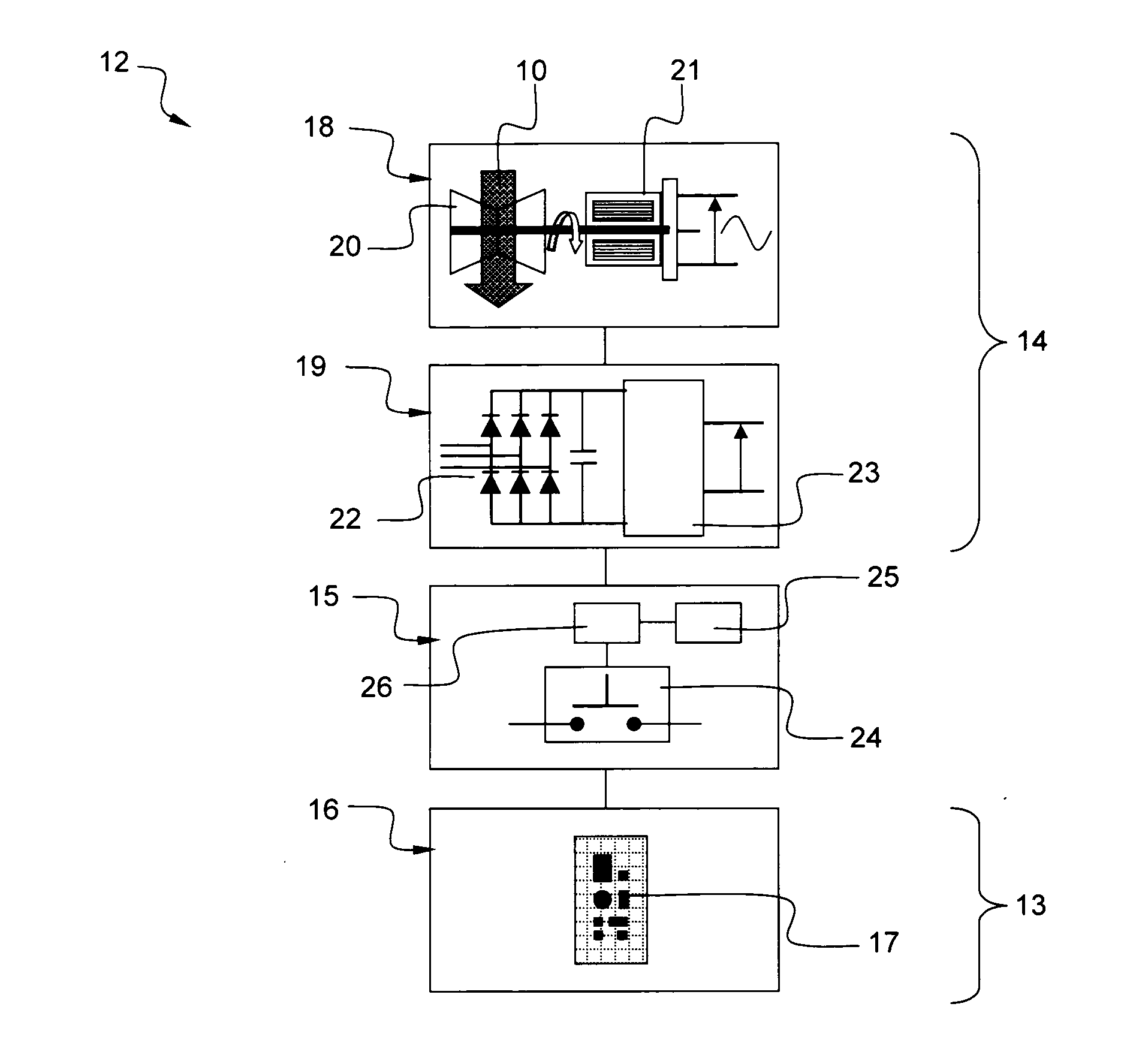
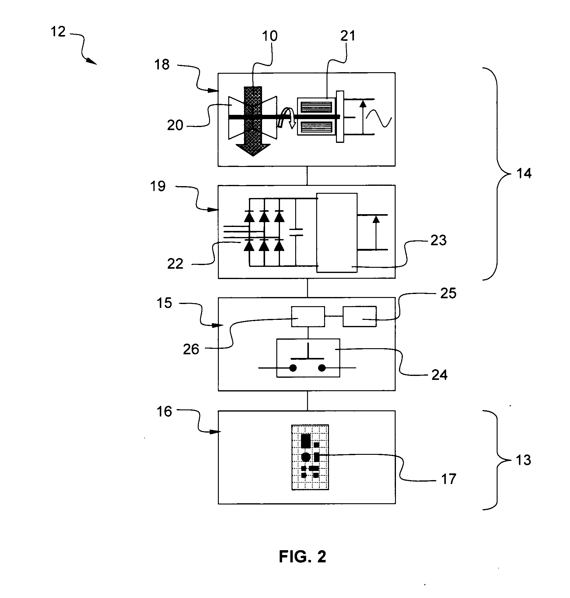
[0021]FIG. 2 is a block diagram schematically representing an electronic apparatus 12 for a downhole tool (9 and 11 shown in FIG. 1). For example, the electronic apparatus 12 may be a part of the logging assembly (11 shown in FIG. 1). The electronic apparatus 12 comprises a first electronic device 13, a second electronic device 14 and a thermally controlled switch 15.
[0022]The first electronic device 13 may comprise a printed circuit board 16 comprising various electronic components 17. For example, the electronic components 17 may be sensors, processors, memories. The sensors may be used to measure properties of the geological formation, the well bore, the drilling fluid, etc. . . . Alternatively, the first electronic device 13 may comprise a plurality of printed circuit board or Multi-chip modules (MCM). The first electronic device 13 operates up to a first maximum operating temperature, for example 200° C. As an example, the first electronic device is implemented by using a standard Silicon integrated circuit technology.
[0023]The second electronic device 14 provides electrical power to the first electronic device 13. The second electronic device 14 may comprise an electrical energy generator 18 coupled to a power supply 19. The electrical energy generator 18 may comprise a turbine 20 coupled to an alternator 21. The turbine 20 rotates when the drilling fluid 10 is circulated into the drill string and downhole tool. Thus, the alternator 21 driven by the turbine 20 generates and alternative signal. The alternative signal delivered by the alternator 21 is delivered to the power supply 19. The power supply 19 may comprise a rectification module 22 coupled to a power converter 23. As an example, the rectification module 22 comprises a Graetz bridge, and the power converter 23 comprises a rectifier and a step-down converter. The power supply 19 delivers an electrical power under the form of a rectified and stepped-down signal (voltage and/or current) suitable for the operation of the first electronic device 13. Advantageously, the second electronic device 14 operates up to a second maximum operating temperature, for example 250° C., at least 220° C. The second maximum operating temperature is higher than the first maximum operating temperature. As an example, the second electronic device is implemented by using a Silicon Carbide SiC device technology, or a Silicon on insulator SOI device technology, or a multichip module MCM technology. It may also be implemented by using a combination of the above mentioned technologies.
[0024]The thermally controlled switch 15 couples the first electronic device 13 to the second electronic device 14. The thermally Controlled switch 15 comprises a switch 24, a temperature sensor 25 and switching module 26. The switch 24 couples the first device 13 to the second device 14. The temperature sensor measures the temperature of the first electronic device 13. Alternatively, the temperature sensor 25 measures the temperature in the vicinity of the first electronic device 13, said temperature being representative of the actual temperature of the first electronic device 13. The switching module 26 operates the switch 24 in dependence of the measured temperature by the temperature sensor 25. For instance, the switch is closed when a measured temperature of the first electronic device 13 is lower than the first maximum operating temperature, e.g. 200° C. Conversely, the switch is open when a measured temperature of the first electronic device 13 is higher than the first maximum operating temperature, e.g. 200° C. Thus, the thermally controlled switch 15 controls supplying electrical power to the electronic device such as to avoid failure due to temperature exceeding the maximum operating temperature of the electronic components of the first electronic device 13. In other word, the electronic components of the first electronic device 13 are only powered up when the temperature is below a predefined temperature.
[0025]FIG. 3 is a block diagram schematically representing an exemplary embodiment of the thermally controlled switch 15 that may be used in the electronic apparatus 12 of FIG. 2.
[0026]The switch 24 comprises a transistor PMOS 27 (MOSFET metal oxide semiconductor field effect transistor) of the P type. The source of the transistor is connected to the power supply 19. The drain of the transistor PMOS 27 is connected to the printed circuit board 16. The gate of the transistor PMOS 27 is connected to the switching module 26. A second resistor 28 of appropriate resistance value is connected between the source and the gate of the transistor PMOS 27.
[0027]The temperature sensor 25 comprise a Platinum resistor 29 connected to the ground and a first resistor 30 of appropriate resistance value. The Platinum resistor 29 is further connected to the switching module 26.
[0028]The switching module 26 comprises a reference voltage 33, a comparator 31 and a transistor NMOS 32. The voltage reference 33 and the temperature sensor 25 are connected to the comparator 31 input. The voltage reference 33 is chosen such as to define the switching temperature. Advantageously, the switching temperature is below the maximum operating temperature of the electronic components of the printed circuit board 16 (first electronic device 13). The transistor NMOS 32 (MOSFET metal oxide semiconductor field effect transistor) is of the N type. The output of the comparator is coupled to the gate of the transistor NMOS 32. The source of the transistor NMOS 32 is connected to the ground. The drain of the transistor NMOS 32 is connected to the switch 24, namely the gate of the transistor PMOS 27 of the switch 24. Thus, when the temperature near the Platinum resistor 29 is below the switching temperature, the switching module 26 controls the switch in a closed position. As a consequence, the power supply 19 is coupled to the printed circuit board 16 which is powered-up. Further, when the temperature near the Platinum resistor 29 is above the switching temperature, the switching module 26 controls the switch in an opened position. As a consequence, the power supply 19 is decoupled of the printed circuit board 16 which is shut-off.
[0029]The elements of the thermally controlled switch 15 are implemented in a Silicon Carbide SiC device technology, or a Silicon on insulator SOI device technology, or a multichip module MCM technology, or a combination of the hereinbefore mentioned technologies.
[0030]FIG. 4 illustrates an example of operation of the electronic apparatus of the invention. The graphic of FIG. 4 shows the temperature of the geological formation TGF (full line) surrounding the downhole tool in dependence of time t. In the present example, this temperature TGF is static around 210° C. The graphic also shows the temperature of the drilling fluid TDF (broken line) circulating into the downhole tool in dependence of time t. In the present example, this temperature TDF is around 190° C. when the drilling fluid is circulating and increases to the static temperature of geological formation TGF when the circulation is stopped. When the drilling fluid is not circulating (t=tCS), the turbine and alternator are not running, and the power supply and the thermally controlled switch are shut down (14 OFF). When the drilling fluid is circulating, the turbine and alternator are running, the power supply and the thermally controlled switch are powered-up (14 ON). On the one hand, the switch couples the power supply to the printed circuit board only if the measured temperature of the printed circuit board is below a predefined temperature (TTS=200° C.) preferably below the maximum operating temperature of the electronic components of the printed circuit board. On the other hand, the printed circuit board is un-powered if the measured temperature of the printed circuit board is above said predefined temperature, preferably just below the maximum operating temperature of the electronic components of the printed circuit board. In this case, as the electronic components of the printed circuit board are un-powered, there is no risk of failure and no self heating effect. In the situation where the circulation of the drilling fluid is resumed (t=tCR) after having been stopped (t=tCS), the drilling fluid circulating inside the downhole tool cool down the temperature inside the downhole tool with a certain latency 34. When the temperature reaches the predefined temperature value TTS, the thermally controlled switch couples the printed circuit board to the power supply and the electronic components are powered (t=tSW). Nevertheless, a sine-qua-non condition remains that although un-powered, the electronic components of the printed circuit board has to survive the high temperature environment.
[0031]Though the invention has been described in relation with a particular example of onshore hydrocarbon well location, it will also be apparent for a person skilled in the art that the invention is applicable to offshore hydrocarbon well location.
[0032]The drawings and their description hereinbefore illustrate rather than limit the invention.
[0033]Any reference sign in a claim should not be construed as limiting the claim. The word “comprising” does not exclude the presence of other elements than those listed in a claim. The word “a” or “an” preceding an element does not exclude the presence of a plurality of such element.

PUM

no PUM

Description & Claims & Application Information

We can also present the details of the Description, Claims and Application information to help users get a comprehensive understanding of the technical details of the patent, such as background art, summary of invention, brief description of drawings, description of embodiments, and other original content. On the other hand, users can also determine the specific scope of protection of the technology through the list of claims; as well as understand the changes in the life cycle of the technology with the presentation of the patent timeline. Login to view more.

Similar technology patents

RFID switch tag

ActiveUS20120280044A1extend operationoperational range be extend
Owner:NEOLOGY INC

Incremental garbage collection for non-volatile memories

ActiveUS20110055455A1extend operation
Owner:APPLE INC

Classification and recommendation of technical efficacy words

  • extend operation

Incremental garbage collection for non-volatile memories

ActiveUS20110055455A1extend operation
Owner:APPLE INC

RFID switch tag

ActiveUS20120280044A1extend operationoperational range be extend
Owner:NEOLOGY INC
Why Eureka
Try Eureka