
RFID switch tag

Active Publication Date: 2012-11-08
NEOLOGY INC
View PDF5 Cites 49 Cited by
  • Summary
  • Abstract
  • Description
  • Claims
  • Application Information

AI Technical Summary

Benefits of technology

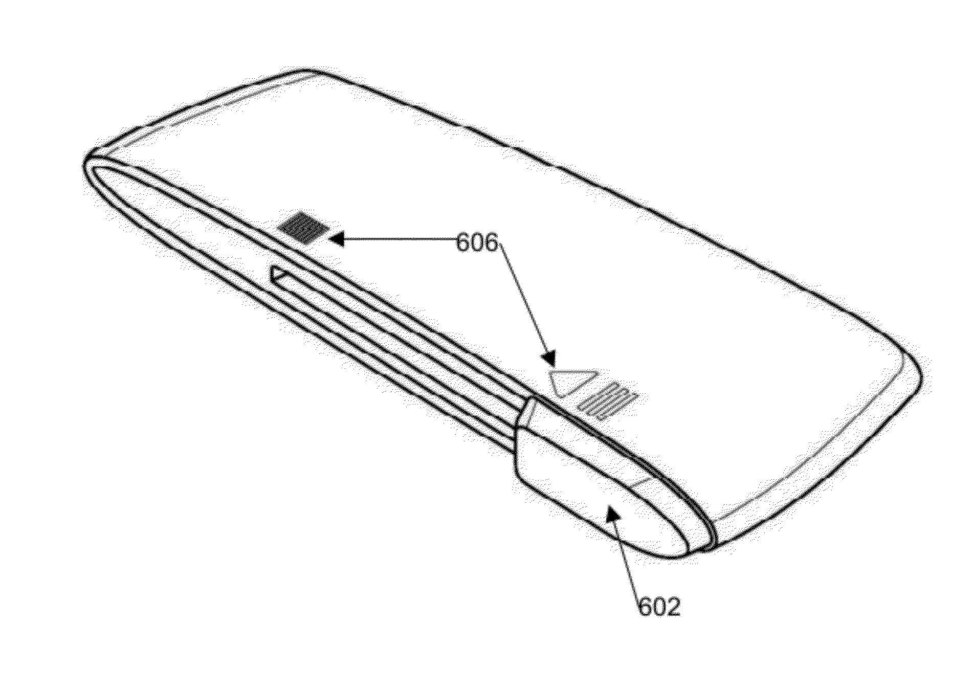
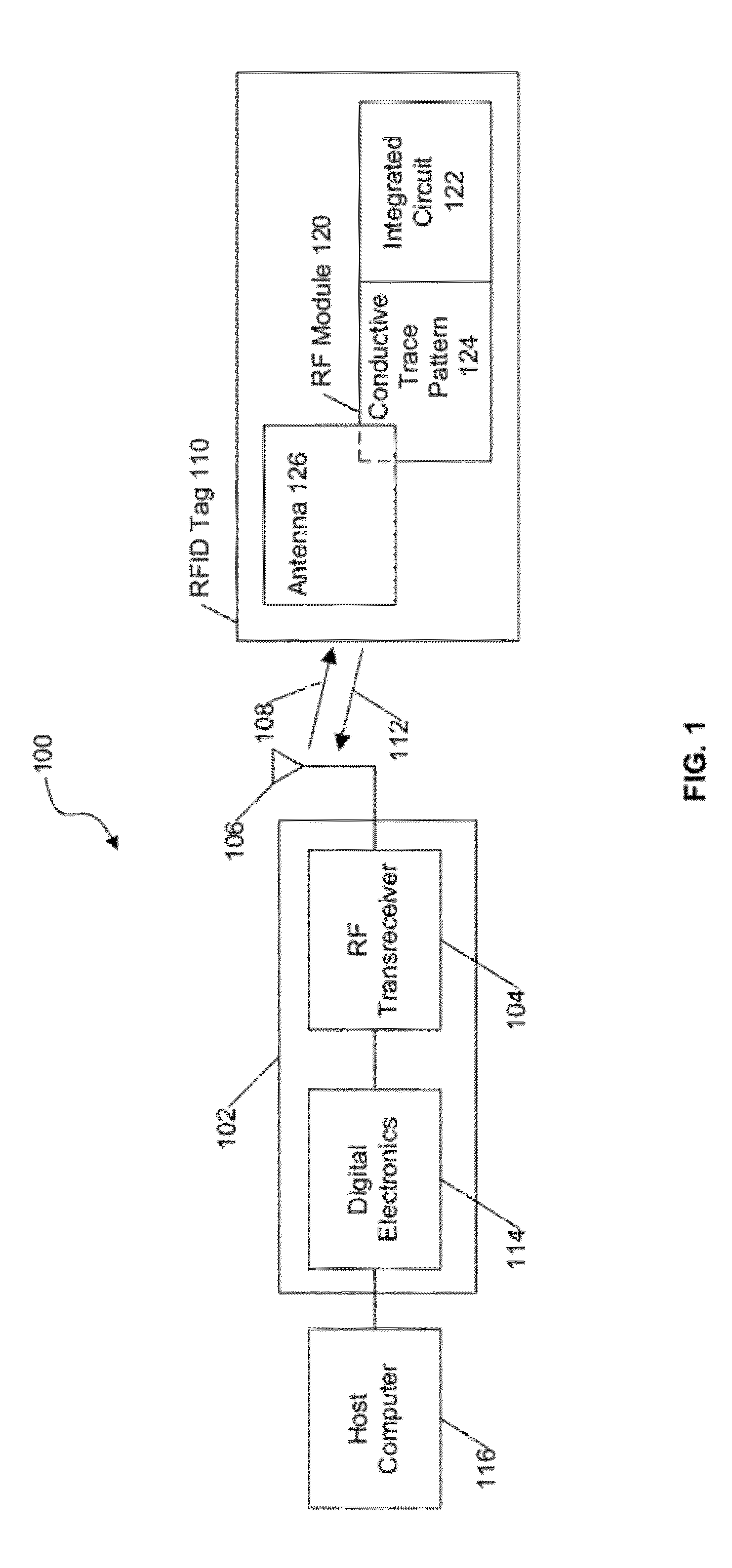
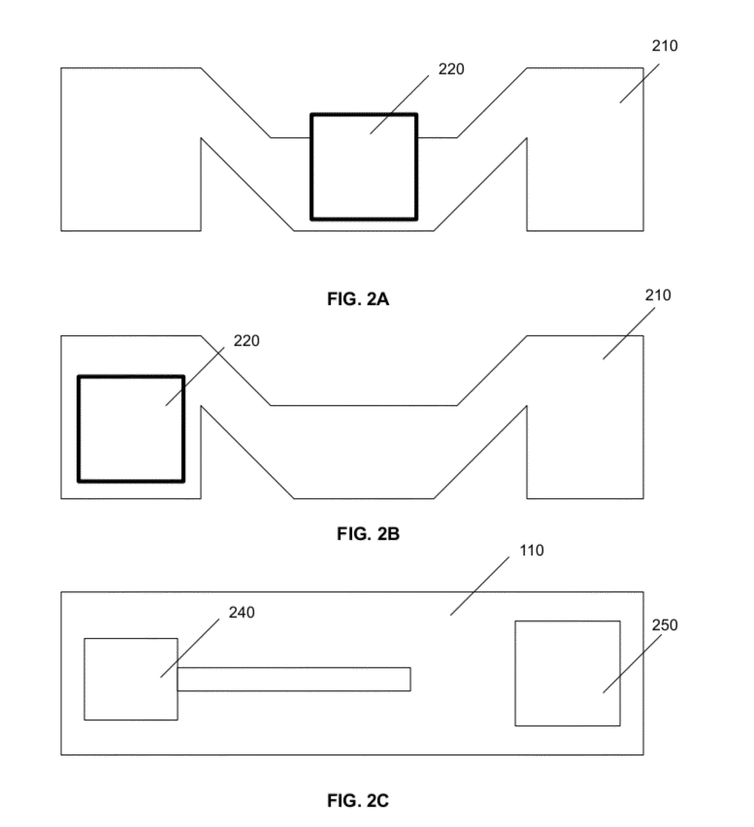
[0008]Various embodiments of the present invention are directed to RFID switch devices. Such RFID switch devices advantageously enable manual activation / deactivation of the RF module. The RFID switch device may include a RF module with an integrated circuit adapted to ohmically connect to a substantially coplanar conductive trace pattern, as well as booster antenna for extending the operational range of the RFID device. The operational range of the RFID switch device may be extended when a region of the booster antenna overlaps a region of the conductive trace pattern on the RF module via inductive or capacitive coupling. In some embodiments, all or a portion of the booster antenna may at least partially shield the RF module when the RFID switch device is in an inactive state. The RFID switch device may further include a visual indicator displaying a first color if the RFID switch device is in an active state and / or a second color if the RFID switch device is in an inactive state.

Problems solved by technology

Conventional RFID tags lack the ability to be deactivated.
However, since the read range of RFID tags can extend up to 30 feet, since an RFID tag does not need to be directly in the line of sight of an RFID reader, this sensitive information may be read by any number of unauthorized individuals as the individual walks through a train station or an airport.
Unless the traveler houses his travel documents within a Faraday shield or other type of electro-resistant casing (which most travelers do not have), the sensitive information stored within the RFID tag remains perpetually at risk of being read by these unauthorized parties.

Method used


Image

  • RFID switch tag
  • RFID switch tag
  • RFID switch tag

Examples


Embodiment Construction

[0034]RFID is an automatic identification method, relying on storing and remotely retrieving data using devices called RFID tags or transponders. The technology relies on cooperation between an RFID reader and an RFID tag. RFID tags can be applied to or incorporated within a variety of products, packaging, and identification mechanisms for the purpose of identification and tracking using radio waves. For example, RFID is used in enterprise supply chain management to improve the efficiency of inventory tracking and management. Some tags can be read from several meters away and beyond the line of sight of the RFID reader.

[0035]Most RFID tags contain at least two parts: One is an integrated circuit for storing and processing information, for modulating and demodulating a radio-frequency (RF) signal, and for performing other specialized functions. The second is an antenna for receiving and transmitting the signal. As the name implies, RFID tags are often used to store an identifier that...


PUM


Abstract

Various embodiments of RFID switch devices are disclosed herein. Such RFID switch devices advantageously enable manual activation / deactivation of the RF module. The RFID switch device may include a RF module with an integrated circuit adapted to ohmically connect to a substantially coplanar conductive trace pattern, as well as booster antenna for extending the operational range of the RFID device. The operational range of the RFID switch device may be extended when a region of the booster antenna overlaps a region of the conductive trace pattern on the RF module via inductive or capacitive coupling. The RFID switch device may further include a visual indicator displaying a first color if the RFID switch device is in an active state and / or a second color if the RFID switch device is in an inactive state.

Description

RELATED APPLICATIONS [0001]This application claims the benefit of U.S. Provisional Application Ser. No. 61 / 483,586 filed May 6, 2011, as well as U.S. Provisional Application Ser. No. 61 / 487,372 filed May 18, 2011, the contents of both of which are incorporated herein by reference in their entireties as if set forth in full.BACKGROUND [0002]1. Field of the Invention[0003]The embodiments described herein relate generally to the field of radio-frequency identification (RFID) devices, and more particularly, to RFID switch tags.[0004]2. Related Art[0005]Conventional RFID tags lack the ability to be deactivated. However, there are certain situations where it is actually desirable to have an RFID tag deactivated. For example, in the context of traveling, RFID tags will often contain sensitive personal information stored within, for instance, an e-Passport, a visa, or a national identification card. Such information may contain the traveler's name, birth date, place of birth, nationality, a...

Claims


Application Information

Patent Timeline
IPC IPC(8): G06K19/073G06K19/077
CPCH01Q1/2225G06K19/041G06K19/07345G06K19/07794G06K19/07701G06K19/07754G06K19/07715G06K19/07703G06K19/07745G06K19/07773
Inventor MULLIS, JOENYALAMADUGU, SHESHI
Owner NEOLOGY INC
Learn More