Error Detection And Correction For Base-Band Wireless Systems

Inactive Publication Date: 2008-05-15
INFRA COM
View PDF11 Cites 14 Cited by
  • Summary
  • Abstract
  • Description
  • Claims
  • Application Information

AI Technical Summary

Benefits of technology

[0013]An aspect of an embodiment of the invention relates to a system and method of encoding data for transmission over a wireless optical link, which allows detection and correction of errors in the transmitted data at the receiver using

Problems solved by technology

On the other hand a diffused connection typically requires larger power emission from the transmitter part of the transceiver, as the diffused infrared signal suffers greater losses than direct and line of sight wireless optical communication systems.
The larger the distance and/or the number of bounces the optical signal needs to traverse between the transmitter and receiver, the more susceptible the link is to errors, as signal strength typically degrades as the square of the distance.
Similarly, a ‘0’ (OFF) bit value may be affected in such a way by added noise and interference causing it to erroneously be detected as a ‘1’ (ON) bit value.
Typically, direct transmission of the raw communication data as binary bits (pulses) like in simple on-off keying (OOK) base-band modulation is problematic, since various reception circuits (e.g. a high pass filter that is used in the receiver device to filter out low frequency noise) tend to have difficulty in dealing with long consecutive sequenc

Method used


Image

  • Error Detection And Correction For Base-Band Wireless Systems
  • Error Detection And Correction For Base-Band Wireless Systems
  • Error Detection And Correction For Base-Band Wireless Systems

Examples


Example

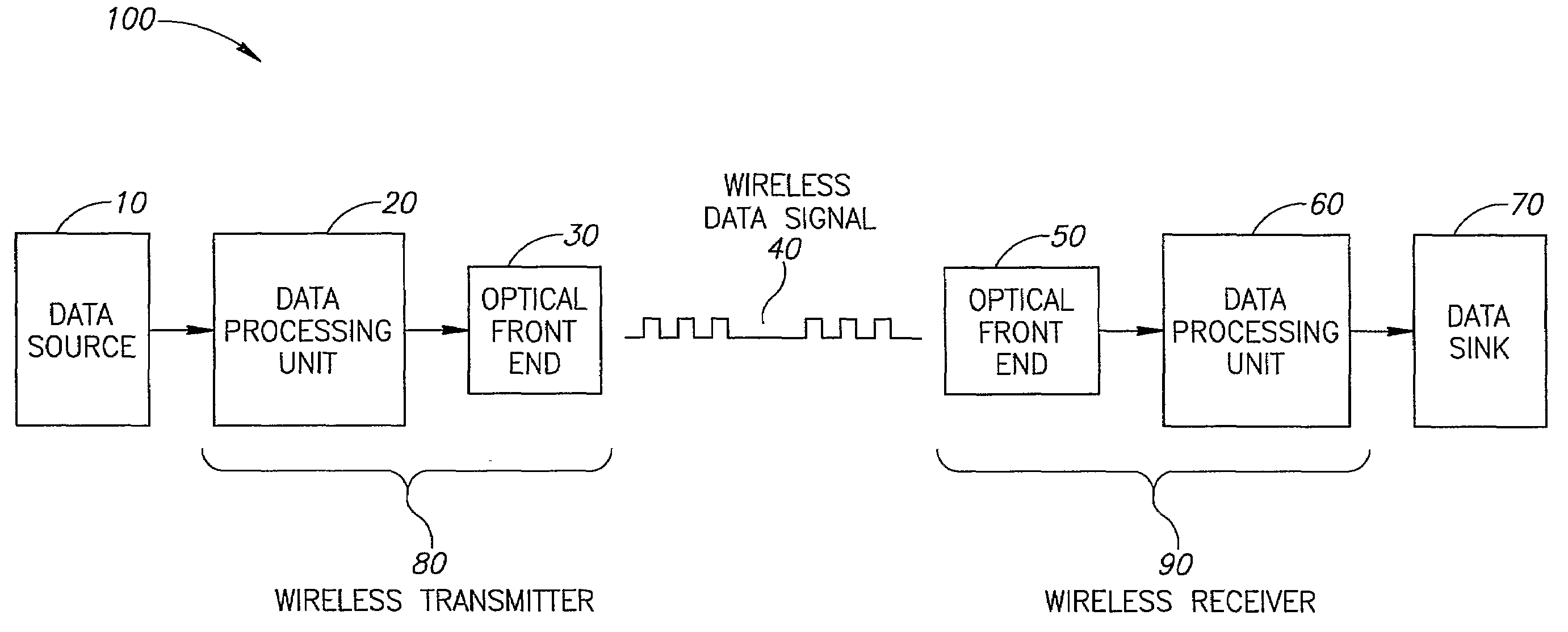
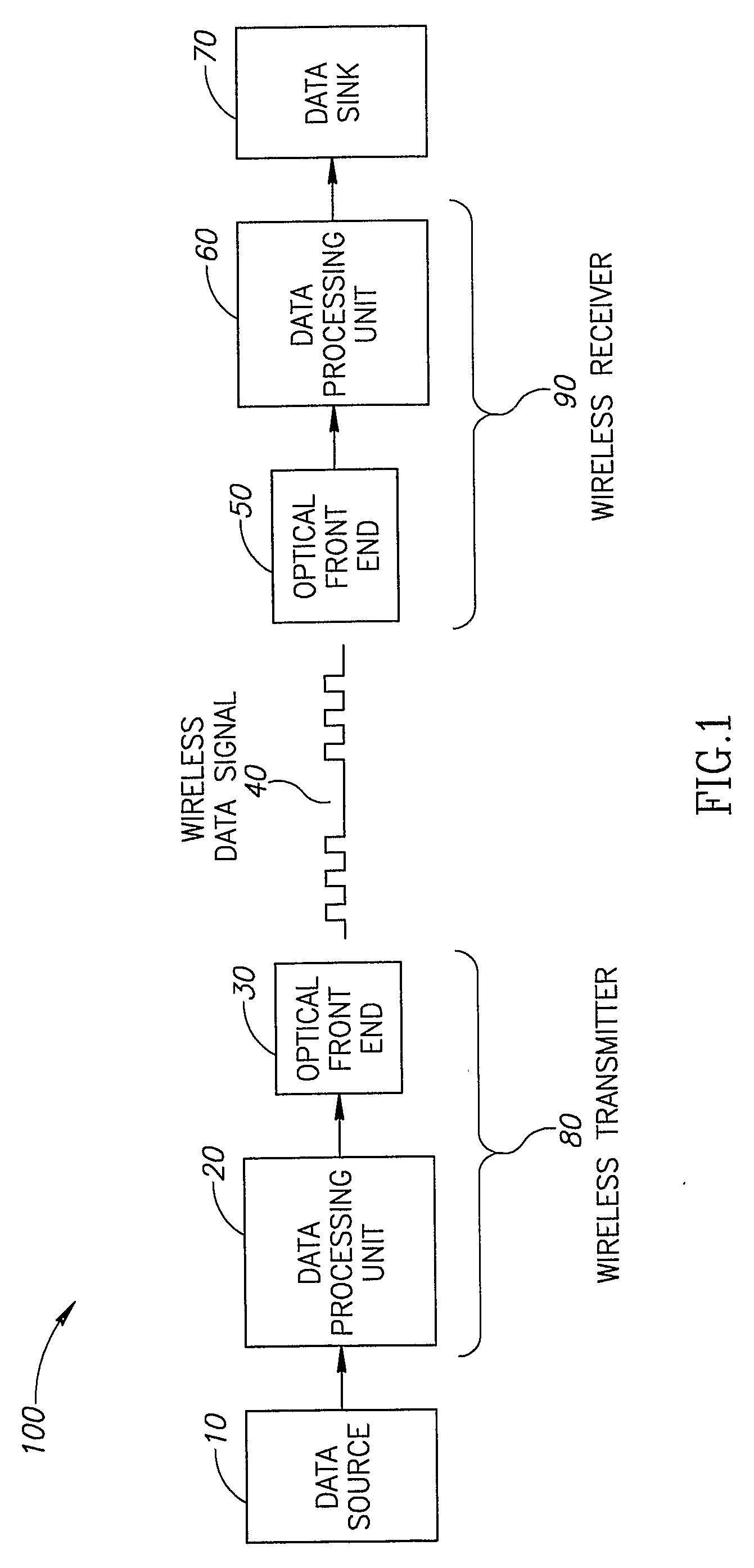
[0065]FIG. 1 is a schematic illustration of a wireless optical communication system 100, according to an exemplary embodiment of the invention. In an exemplary embodiment of the invention, system 100 comprises an IR wireless transmitter 80 and an IR wireless receiver 90. Optionally, IR wireless transmitter 80 receives data from a data source 10 and transmits a wireless data signal 40 to IR wireless receiver 90. In an exemplary embodiment of the invention, wireless data signal 40 may be affected by physical phenomenon, for example ambient natural or artificial light in the room or enclosure, or the distance between the transmitter and receiver, causing attenuation to wireless data signal 40 and thus errors in the signal received by IR wireless receiver 90. In an exemplary embodiment of the invention, wireless data signal 40 is encoded using a robust modulation and encoding method, comprising codewords, which replace a specific number of bits (e.g. symbols) of the original data. The r...


PUM


Abstract

A method of encoding, transmitting and decoding data over a wireless medium, including, selecting a number of bits N representing a symbol, creating a set of at least 2 to the power of N equal sized codewords with a larger number of bits than N, representing the 2 to the power of N possible combinations of N bit symbols, receiving a stream of data, replacing every N bit symbol from the stream of data with its representative codeword from the created set, transmitting the codewords using a faster transmission bit rate such that the transmission time allocated for each codeword is substantially the same as the time duration required to transmit the original bits it replaced.

Description

RELATED APPLICATIONS[0001]The application claims priority from U.S. provisional application No. 60 / 641,887 filed on Jan. 6, 2005.FIELD OF THE INVENTION[0002]The present invention relates generally to a robust method of encoding and decoding wireless transmissions.BACKGROUND OF THE INVENTION[0003]The use of wireless communication between different parts of a device and / or different devices has many advantages. Wireless communication simplifies installation. It eliminates the need to layout cables or wires between the devices, as well as identify and hook up to specific connection sockets. It allows greater freedom in positioning of the device, and the use of mobile or hand held devices. Some examples of such devices are a remote control for a TV (or other device), a computer and its input and / or output peripheral devices (e.g. mouse, keyboard, screen, printer) and an audio source device and its respective surround speakers.[0004]Commonly, wireless devices use RF (radio frequency) or ...

Claims


Application Information

Patent Timeline
IPC IPC(8): H04B14/04H04B10/11H04B10/118H04B10/516H04B10/524H04B10/54H04B10/61H04B10/85
CPCH04L25/4902H03M13/03
Inventor SHAANAN, TAMIRFREILICHER, LEV
Owner INFRA COM
Why Eureka
Try Eureka