Optical transmission apparatuses, methods, and systems

a technology of optical transmission and transmission apparatus, applied in the direction of electromagnetic transmission, electrical equipment, transmission, etc., can solve the problems of limited operation bandwidth of edfas, limited benefit of first option, transmission and detection errors in optical systems, etc., and achieve the effect of robust optical communication

Inactive Publication Date: 2011-06-02
LEVEL 3 COMM LLC
View PDF58 Cites 56 Cited by
  • Summary
  • Abstract
  • Description
  • Claims
  • Application Information

AI Technical Summary

Benefits of technology

[0016]The present invention introduce a paradigm shift from the conventional approach of hardware defined optical transport to an “agile coherent optical modem” [ACOM] approach to optical communications by employing a software configurable and adaptive technologies to the transport system. The ACOM generates agile RF waveforms and data rates on a generic opto-electronic hardware platform. By employing advanced communication techniques to the optical domain such as wavelength agility, waveform agility, and symbol rate agility, it is possible to enable robust optical communications. The ACOM allows for the transport capacity of a communications link to be varied, thereby accommodating variations in transport conditions, range, opacity, etc.
[0017]The ACOM includes four key elements: a) an optical vector modulator in the transmitter, b) a coherent optical receiver, c) a programmable electronics platform, and d) wavelength translation, if necessary. The transmitter combines arbitrary waveform generation with programmable electronics and the capability to map an RF waveform (i.e. both amplitude and phase) into the optical domain. A coherent receiver allows the recovery of the amplitude and phase information, which together with programmable electronics and adaptive communications between the transmitter and receiver, enables the ACOM.

Problems solved by technology

External modulation is more often used for higher speed transmission systems, because the high speed direct modulation of a source often causes undesirable variations in the wavelength of the source.
The wavelength variations, known as chirp, can result in transmission and detection errors in an optical system.
Generally, only one of the mirror images is required to carry the signal and the other image is a source of signal noise that also consumes wavelength bandwidth that would normally be available to carry information.
Similarly, the carrier wavelength, which does not carry the information, can be a source of noise that interferes with the subcarrier signal.
The first option currently provides only limited benefit, because most optical systems use erbium doped fiber amplifiers [EDFAs] to amplify the optical signal during transmission.
EDFAs have a limited bandwidth of operation and suffer from non-linear amplifier characteristics within the bandwidth.
Difficulties with the second option include controlling optical sources that are closely spaced to prevent interference from wavelength drift and nonlinear interactions between the signals.
A further difficulty in WDM fiber transport systems is that chromatic dispersion, which results from differences in the speed at which different wavelengths travel in optical fiber, can also degrade the optical signal.
However, the decreased dispersion of the optical signal allows for increased nonlinear interaction, such as four wave mixing, to occur between the wavelengths that increases signal degradation.
The many difficulties associated with increasing the number of wavelength channels in WDM and free-space systems, as well as increasing the transmission bit rate have slowed the continued advance in communications transmission capacity.

Method used


Image

  • Optical transmission apparatuses, methods, and systems
  • Optical transmission apparatuses, methods, and systems
  • Optical transmission apparatuses, methods, and systems

Examples


Embodiment Construction

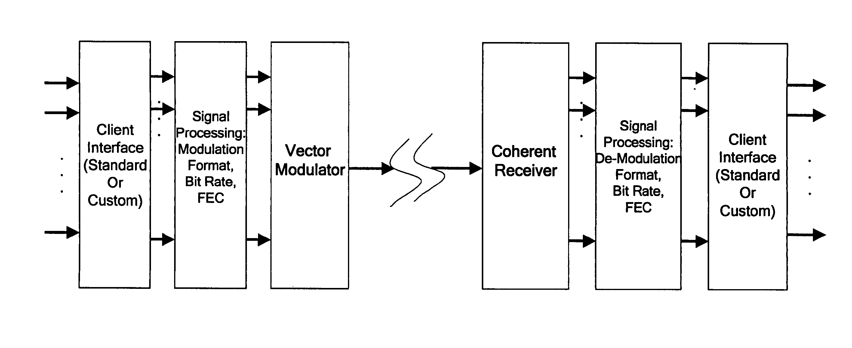
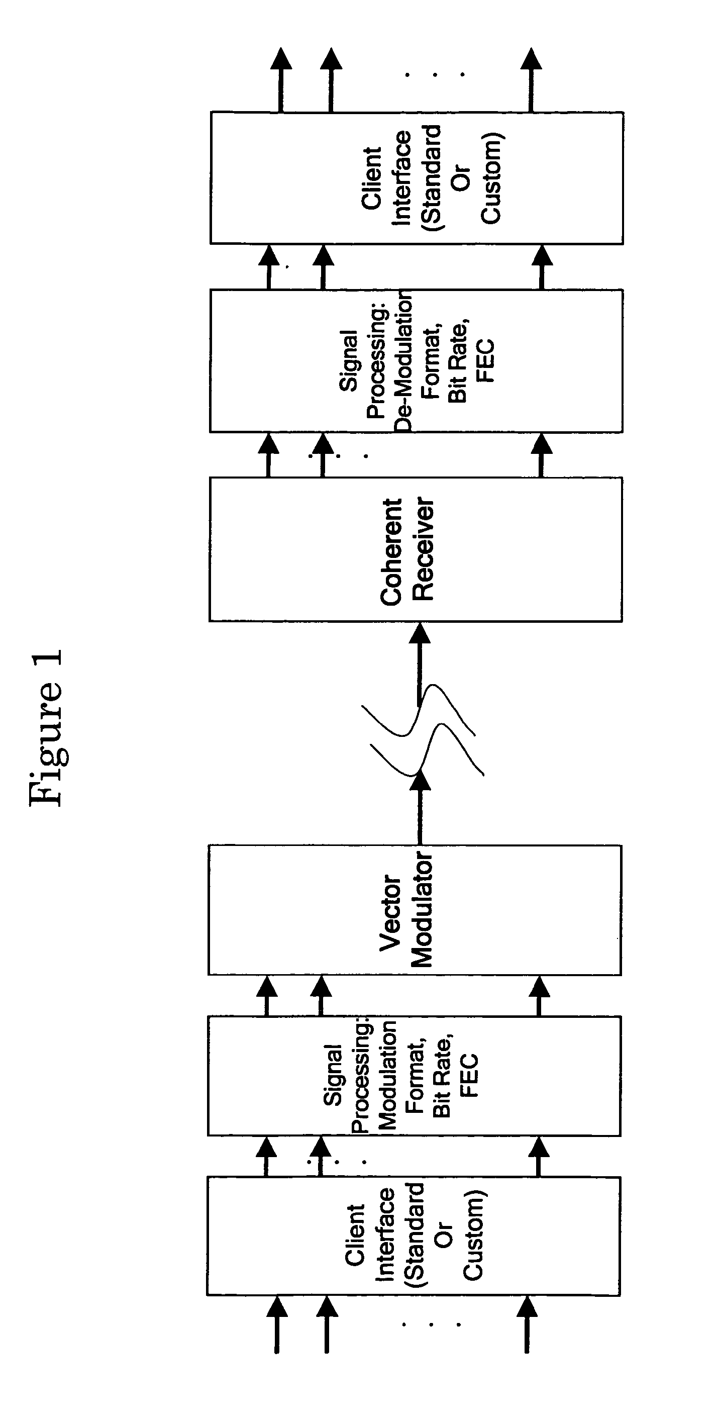
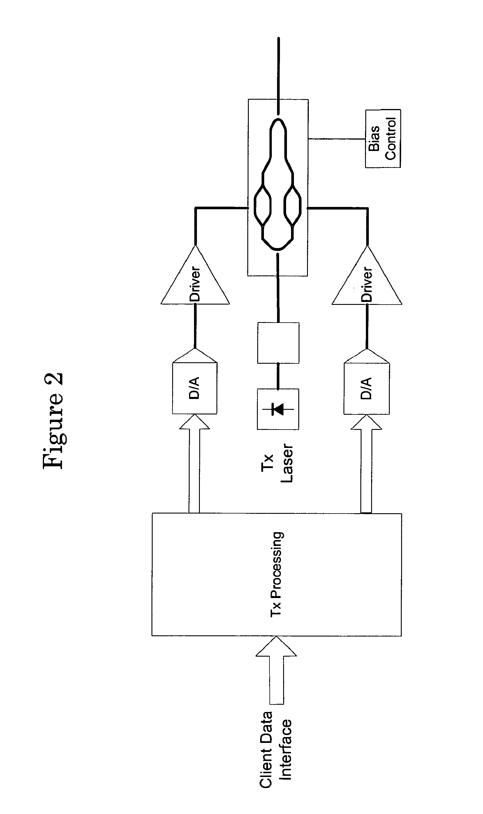
[0057]FIG. 1 illustrates an ideal ACOM with an “agile optical transmitter” [AOT] and a “agile coherent optical receiver” [ACOR]. The AOT (FIG. 2) is comprised of a client interface, a signal-processing unit [SPU], and an optical transport unit generally including a vector modulator or other device that converts any RF waveform into an optical signal at any wavelength. See U.S. Pat. No. 6,118,566, which is incorporated herein by reference, for an example of optical upconversion of RF waveforms. The signal-processing unit is a flexible digital signal-processing [DSP] unit that can generate any RF waveform in any shape and at any data rate. The signal-processing unit also has the capability of scrambling data or pre-distorting the signals for security purposes, forward error correction [FEC] for improved link communication, adaptive modulation for optimizing the data rate and modulation format, and polarization control of the signals in an appropriately designed vector modulator. The c...


PUM


Abstract

Apparatuses, systems, and methods are disclosed that provide for an agile coherent optical modem that can generate agile RF waveforms and data rates on a generic opto-electronic hardware platform. An “agile coherent optical modem” [ACOM] approach to optical communications by employing a software configurable and adaptive technologies to the transport system. The ACOM generate agile RF waveforms and data rates on a generic opto-electronic hardware platform. By employing advanced communication techniques to the optical domain such as wavelength agility, waveform agility, and symbol rate agility, it is possible to enable robust optical communications. The ACOM allows for the transport capacity of a communications link to be varied, thereby accommodating variations in transport conditions, range, opacity, etc.

Description

CROSS-REFERENCE TO RELATED APPLICATIONS[0001]This application is a divisional of and claims benefit of priority to U.S. Non-Provisional patent application Ser. No. 11 / 446,392, filed Jun. 2, 2006, which is incorporated herein by reference in its entirety for all purposes. U.S. Non-Provisional patent application Ser. No. 11 / 446,392 claims benefit of priority to U.S. Provisional Patent Application No. 60 / 686,551, filed on Jun. 2, 2005, and U.S. Provisional Patent Application No. 60 / 711,306, filed Aug. 25, 2005, both of which are incorporated herein by reference in their entirety for all purposes.STATEMENT REGARDING FEDERALLY SPONSORED RESEARCH OR DEVELOPMENT[0002]Not applicable.BACKGROUND OF THE INVENTION[0003]The present invention is directed generally to the transmission of information in communication systems including fiber and free-space systems. More particularly, the invention relates to transmitting information via optical signals in optical transmission systems and transmitter...

Claims


Application Information

Patent Timeline
Patent Type & Authority Applications(United States)
IPC IPC(8): H04B10/00
CPCH04B10/5055H04B10/541H04B10/5561H04B10/60H04B10/11H04B10/614H04B10/6151H04B10/677H04B10/611H04B10/65
Inventor ZANONI, RAYMONDCOPELAND, DAVID J.PRICE, ALISTAIR J.
Owner LEVEL 3 COMM LLC
Why Eureka
Try Eureka