Tubular connector

Inactive Publication Date: 2012-04-26
CLAXTON ENG SERVICES
View PDF38 Cites 23 Cited by
  • Summary
  • Abstract
  • Description
  • Claims
  • Application Information

AI Technical Summary

Benefits of technology

[0023]It is, however, more often the case that the tubular member is not predictably round, having significant high and low radial points around its circumference. Therefore, it is advantageous if the movement means for each block is independent of the move

Problems solved by technology

However placing a weld on the pipe wall will always have the potential to interfere with the structural integrity of the pipe.
If the pipe wall can be pierced, it may be possible to attach a component by passing a fastening through the pipe, but this also interferes with the strength of the pipe.
Although many prior art designs of tubular connector have been proposed, many of these are quite complex mechanically, having spring based or hydraulic drive mechanisms to co

Method used


Image

  • Tubular connector
  • Tubular connector
  • Tubular connector

Examples


first embodiment

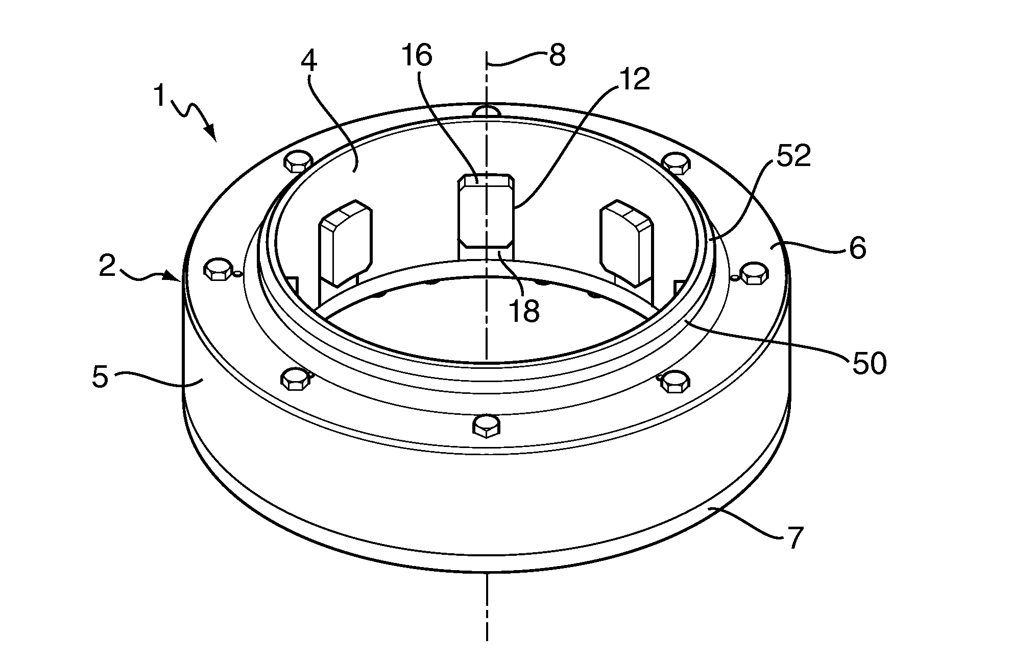
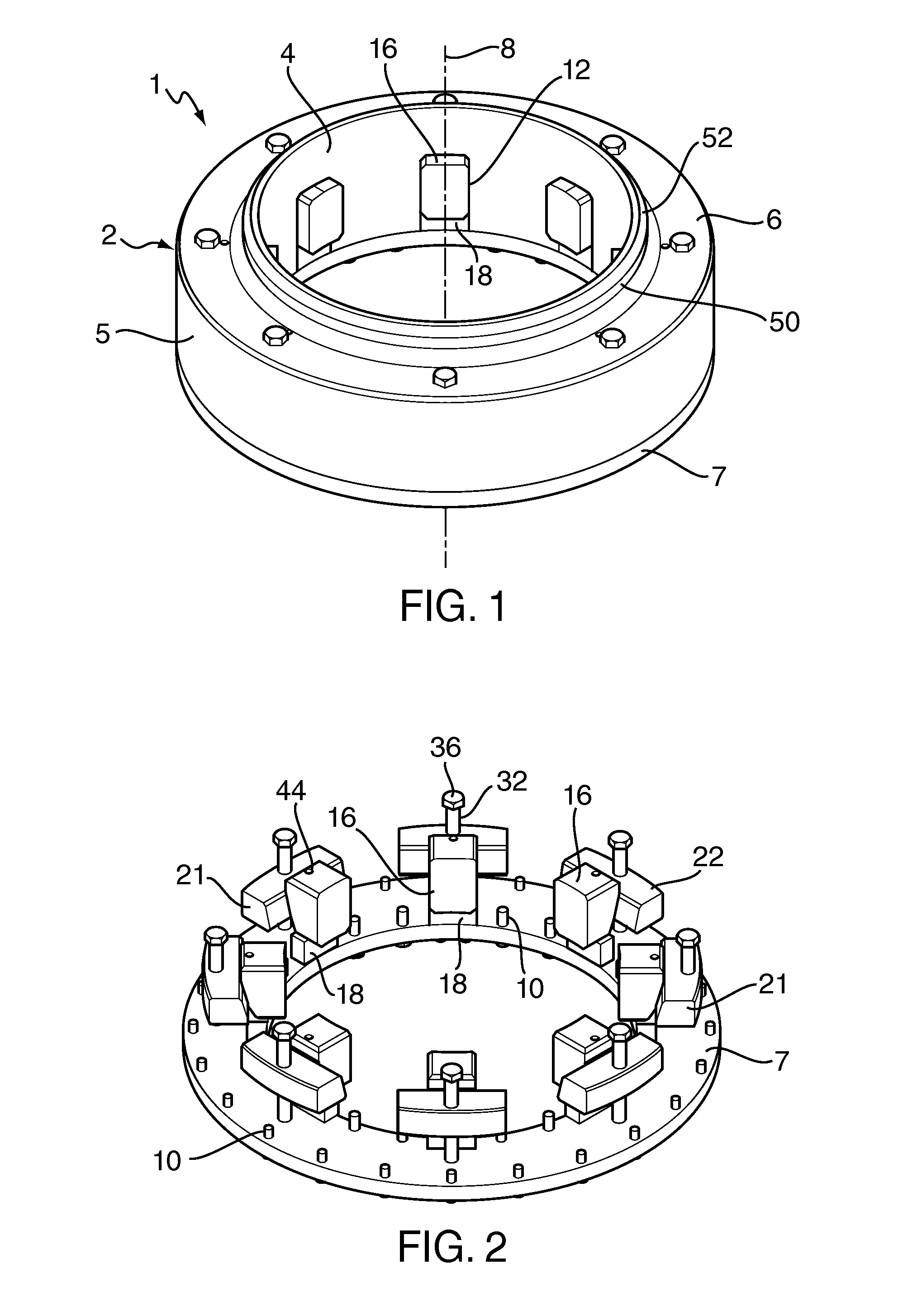
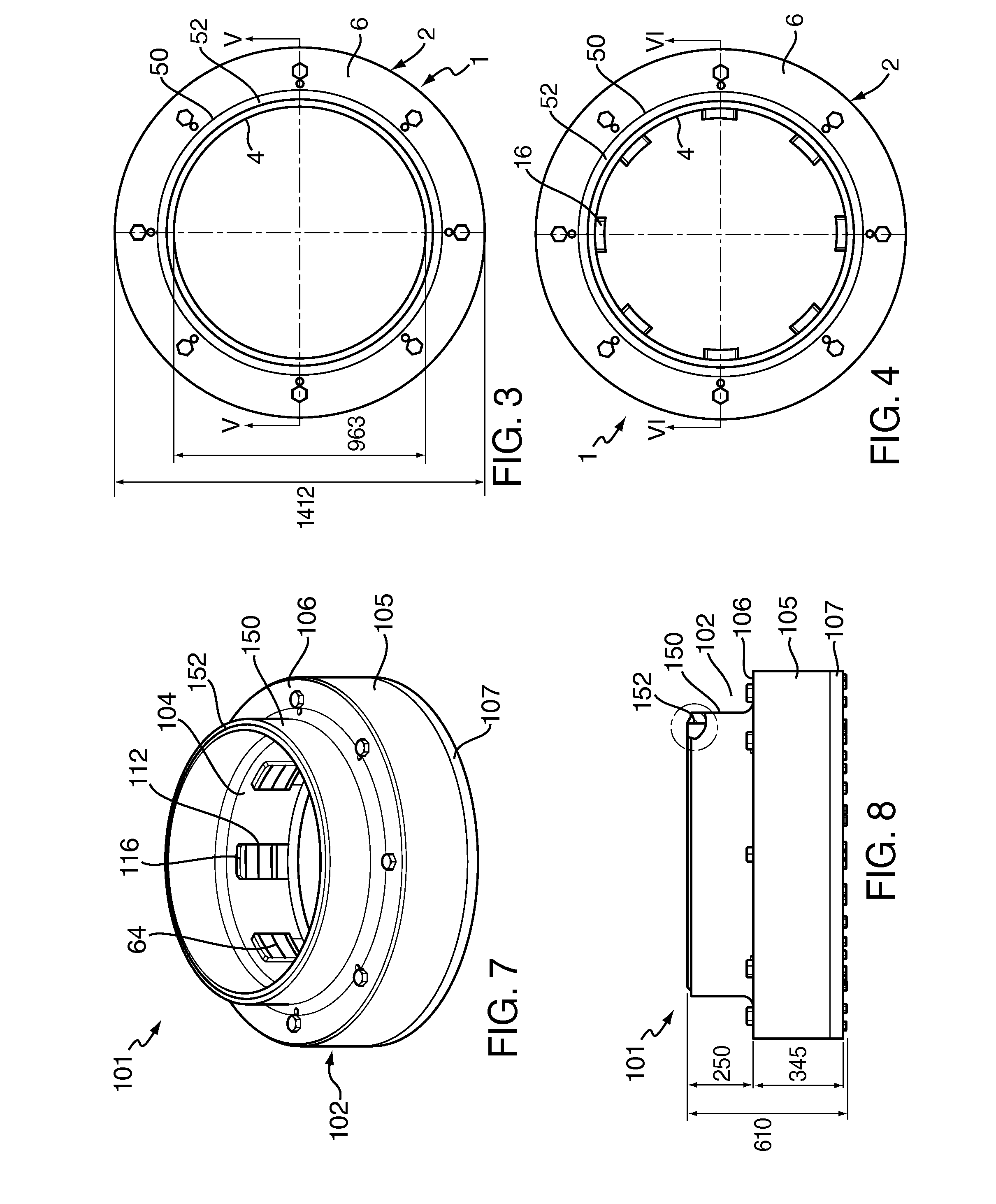
[0048]FIGS. 1 to 6 show a clamping connector 1 for affixing to a tubular member. The connector 1 has a main body portion in the form of a collar 2 that has a cylindrical inner wall 4, a cylindrical outer wall 5 concentric with the inner wall, an annular top wall 6 and an annular bottom wall 7 which is a plate removeably affixed to the inner and outer walls. The cylindrical inner and outer walls 4, 5 of the collar define a collar axis 8, with the top wall 6 and bottom plate 7 lying in parallel planes that are perpendicular to the collar axis.

[0049]The inner, outer and top walls 4, 5, 6 are integrally formed, being machined from a block of steel. The bottom plate 7 is bolted to the inner and outer walls 4, 5 by a series of bolts 10 that extend around the annular bottom plate and that engage in similarly threaded bores 11 in the inner and outer walls 4, 5. Together, the top and bottom walls tie the inner and outer walls of the collar together.

[0050]The inner wall 4 has a plurality of a...

second embodiment

[0068]FIGS. 11 to 14 show various views of a drilling platform structure 60 having a plurality of vertical tubular frame members each of which has butt welded at its lower end a clamping connector. In this example, the clamping connector is according to the invention 101, but either of the other two embodiments of clamping connector 1, 201 could be used in place of this. The clamping connector 101 once welded to each of the vertical tubular frame members permits connection to a similar array of vertically extending underwater tubular members (not shown).

[0069]To help resist corrosion, the external surfaces of the clamping connector 1, 101, 201 may be coated with a suitable corrosion protective coating and a cathodic protection system such as anodes attached.

[0070]FIGS. 15 to 17 show two views of a conductor supported drilling template 70, having a plurality of guide funnels 71 to 75, with a clamping connector. In this example, the clamping connector 101 is according to the second em...


PUM

PropertyMeasurementUnit
Angleaaaaaaaaaa

Abstract

The invention relates to a connector (1) for clamping a component around a tubular member (30) and to a method of using such a connector. The clamping connector (1) comprises a collar (2), a plurality of movable dogs (16) mounted in the collar and actuation means for driving the movement of the dogs. The collar (2) has an inner wall (4) and an outer wall 5, the inner wall being adapted to surround the tubular member (30) with a gap (56) between an outer surface of the inner wall (4) and an outer surface (28) of the tubular member. The inner wall (4) has a plurality of apertures (12) each aperture leading to a passage (14) through the inner wall. Each of the dogs (16) is slidably seated in one of the passages (14) for movement in a radial direction with respect to the tubular member (30). Around each passage (14) the inner wall (4) is spaced apart from an inner surface (25) of the outer wall (5). The actuation means includes a movable block (22) within the space (20) between the inner and outer walls (4, 5) and movement means (32) for moving the block in an axial direction with respect to the tubular member. Each block (22) has a radially outer surface (23) in sliding contact with the inner surface (25) of the outer wall (5) when each block is moved in the axial direction. Each block also has a radially inner surface (24) and each dog has a corresponding radially outer surface (26) that are in sliding contact with each other. At least one pair (24, 26) of these contacting sliding surfaces are oppositely inclined with respect to each other so that the relative axial movement of the block (22) and the dog (16) causes the dog to be driven in a radially inwardly direction across the gap (56) to grip the tubular member (30).

Description

BACKGROUND[0001]a. Field of the Invention[0002]The invention relates to a connector for clamping a component around a tubular member and to a method of using such a connector.[0003]b. Related Art[0004]It is known to attach a component to a tubular pipe or the like by welding the component directly to the pipe wall or by welding a bracket or lug to the pipe wall and then attaching the component to the bracket or lug. However placing a weld on the pipe wall will always have the potential to interfere with the structural integrity of the pipe. If the pipe wall can be pierced, it may be possible to attach a component by passing a fastening through the pipe, but this also interferes with the strength of the pipe.[0005]Various tubular connectors have therefore been proposed which can be affixed to the outer wall of a tubular pipe or the like by tightening a component of the connector to grip the outer wall of the pipe. The connector then provides a support or a fixing for a main component...

Claims


Application Information

Patent Timeline
IPC IPC(8): E02B17/06B23P11/00F16L3/10
CPCF16L25/06Y10T29/5367F16B7/0493Y10T29/49826Y10T403/7066Y10T29/49947Y10T403/7067F16L21/08E02B17/027F16B2/14F16L3/1211
Inventor PATTERSON, ROWAN WARWICKMARCANTONIO, MATTHEWLEYDEN, CONOR PATRICK
Owner CLAXTON ENG SERVICES
Why Eureka
Try Eureka