Line replaceable, fly-by-wire control columns with push-pull interconnect rods

a technology of push-pull interconnect rods and control columns, which is applied in the direction of manual control with single controlling member, mechanical control devices, instruments, etc., can solve the problems of increased maintenance costs of the pulley system, and the need for maintenance of the entire aircraft, and achieve the effect of increasing the force profil

Active Publication Date: 2012-04-26
WOODWARD MPC
View PDF0 Cites 31 Cited by
  • Summary
  • Abstract
  • Description
  • Claims
  • Application Information

AI Technical Summary

Benefits of technology

[0007]In one aspect, the invention provides a new and improved control input system for an aircraft. In one aspect, the system includes a pair of control columns that are selectively interconnected such that manipulation of one of the control columns is translated to the other one of the control columns. In another aspect of some embodiments, the system includes a disconnect arrangement for each of the degrees of freedom (pitch and roll) of the system that operably disconnects the two control columns such that the two control columns can operate independently such as in the event of failure of one of the control columns. In a further aspect of some embodiments, the system may also include a discontinuous force profile for a restoring force mechanism that provides tactile feedback to the pilots simulating resistance provided by control surfaces of the aircraft. In a further aspect of other embodiments, the system may also include an autopilot lockout mechanism that increases the force profile experienced by the pilots when autopilot mode is entered.
[0012]In one implementation, the latch arrangement includes a pivoting catch and a preload spring. The preload spring extends between the pivoting catch and the connection link. In the coupled state, the pivoting catch is in a first position and tensions the preload spring to bias the connection link into engagement with the clevis link. In the decoupled state, the pivoting catch is in a second position and reduces the tension of the preload spring to allow the connection link to be decoupled from the clevis link.
[0016]In a further embodiment, an autopilot lockout mechanism is provided. The autopilot lockout mechanism is associated with a selected one of pitch or roll. The autopilot lockout mechanism provides increased resistance that must be overcome to manipulate the first and second control columns along the selected one of the pitch axis or roll axis when autopilot is activated.
[0025]In a more particular embodiment, the LRU control column comprises a pitch autopilot lockout mechanism and a roll autopilot lockout mechanism. The pitch autopilot lockout mechanism increases the resistance opposing motion of the control stick from the neutral position about the pitch axis when autopilot is activated. The roll autopilot lockout mechanism increases resistance opposing motion of the control stick from the neutral position about the pitch axis when autopilot is activated.
[0026]In a further embodiment, the control column is an LRU, further including an autopilot lockout mechanism associated with a selected one of pitch or roll. The autopilot lockout mechanism providing increased resistance that must be overcome to manipulate the control columns along the selected one of the pitch axis or roll axis when autopilot is activated.

Problems solved by technology

Unfortunately, when there was a problem in one of the control columns, the entire aircraft would have to taken in for maintenance because the control column could not be removed due to the system of cables.
Further, the complex pulley system provided for increased maintenance costs.

Method used


Image

  • Line replaceable, fly-by-wire control columns with push-pull interconnect rods
  • Line replaceable, fly-by-wire control columns with push-pull interconnect rods
  • Line replaceable, fly-by-wire control columns with push-pull interconnect rods

Examples


Embodiment Construction

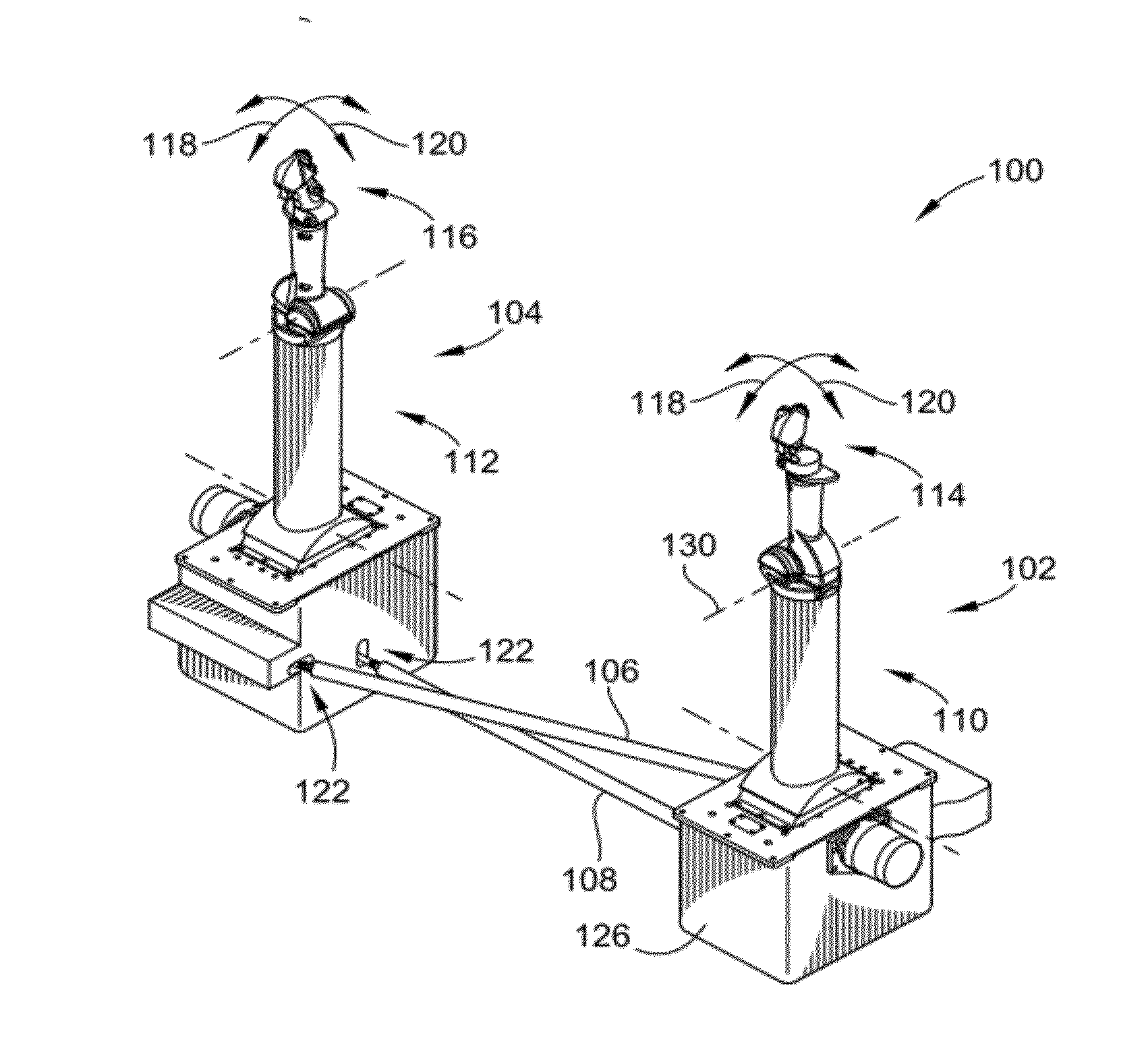
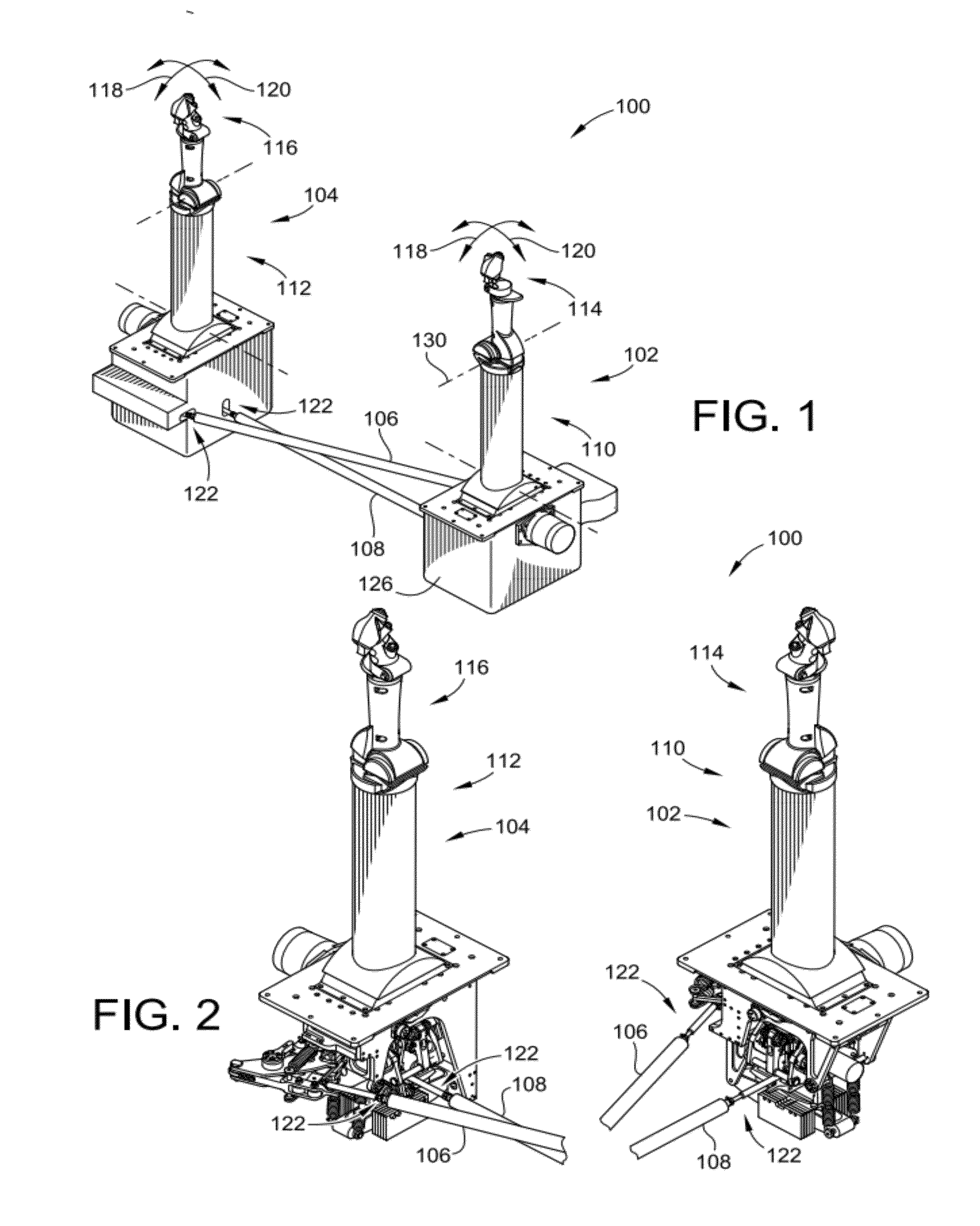
[0041]FIG. 1 illustrates an aircraft control input system 100 (hereinafter “control system 100”) according to an embodiment of the present invention. The control system 100 is used by the pilot and copilot to input control signals to the aircraft. For instance, the control system 100 is used by the pilot and copilot to control, among other things, the pitch and roll of the aircraft. The illustrated embodiment is considered a “fly-by-wire” unit in that the control system 100 includes a plurality of sensors that sense manipulations of the control system 100 by the pilots and converts those manipulations into electrical signals. The electrical signals are then sent to the actual devices of the aircraft that adjust the pitch or roll of the aircraft by adjusting the position of the control surfaces of the aircraft. This is unlike prior systems where the control system included a plurality of cables and pulleys that coupled the control system directly to the control surfaces of the aircra...


PUM


Abstract

A control input system is provided. The system includes a pair of control columns that are selectively interconnected such that manipulation of one of the control columns is translated to the other one of the control columns. The system includes a disconnect arrangement for each of the degrees of freedom (pitch and roll) of the system that operably disconnects the two control columns such that the two control columns can operate independently such as in the event of failure of one of the control columns. The system may also include a discontinuous force profile for a restoring force mechanism that provides tactile feedback to the pilots simulating resistance provided by control surfaces of the aircraft. The system may also include an autopilot lockout mechanism that increases the force profile experienced by the pilots when autopilot mode is entered.

Description

FIELD OF THE INVENTION[0001]This invention generally relates to fly-by-wire control columns.BACKGROUND OF THE INVENTION[0002]Airplanes and other aircraft typically have built in redundancy such as the ability to be flown by a pilot or co-pilot. As such, the aircraft typically includes a pair of control input devices for the pilots to input control commands to the aircraft. These control input devices are often referred to as control columns. The control columns can be used by the pilot to input control commands that include the pitch and roll of the aircraft as it is flying through the air.[0003]Typically, each control column includes a stick that the pilot manipulates to generate a desired control signal relating to the desired amount of pitch or roll for the aircraft.[0004]To provide tactile cues to the other pilot, the control columns are typically coupled together such that changes in position of one of the sticks results in the same or similar changes in position of the other s...

Claims


Application Information

Patent Timeline
Patent Type & Authority Applications(United States)
IPC IPC(8): B64C13/12G05G9/047
CPCB64C13/12Y10T74/20201B64C13/10B64C13/503B64C13/345
Inventor BURROUGHS, MICHAEL A.HUTCHISON, JOEL M.STACHNIAK, DARRYL S.
Owner WOODWARD MPC
Why Eureka
Try Eureka