Gasket for piping

Inactive Publication Date: 2012-04-26
SARKISIAN ARMOND +2
View PDF38 Cites 26 Cited by
  • Summary
  • Abstract
  • Description
  • Claims
  • Application Information

AI Technical Summary

Benefits of technology

[0066]the radially extending protuberances are positioned near the first and second chamfered openings a distance away from the outer edge rim

Problems solved by technology

Regrettably, most conventional gaskets 100 suffer from obvious disadvantages in that it is extremely difficult, and as a consequence, labor intensive and time consuming, to insert the pipe segments inside the gaskets 100.
It should be noted that the difficulty of installation is compounded when the pipe segments are very long and cannot be simply held in position with appropriat

Method used


Image

  • Gasket for piping
  • Gasket for piping
  • Gasket for piping

Examples


Example

[0082]The detailed description set forth below in connection with the appended drawings is intended as a description of presently preferred embodiments of the invention and is not intended to represent the only forms in which the present invention may be constructed and / or utilized.

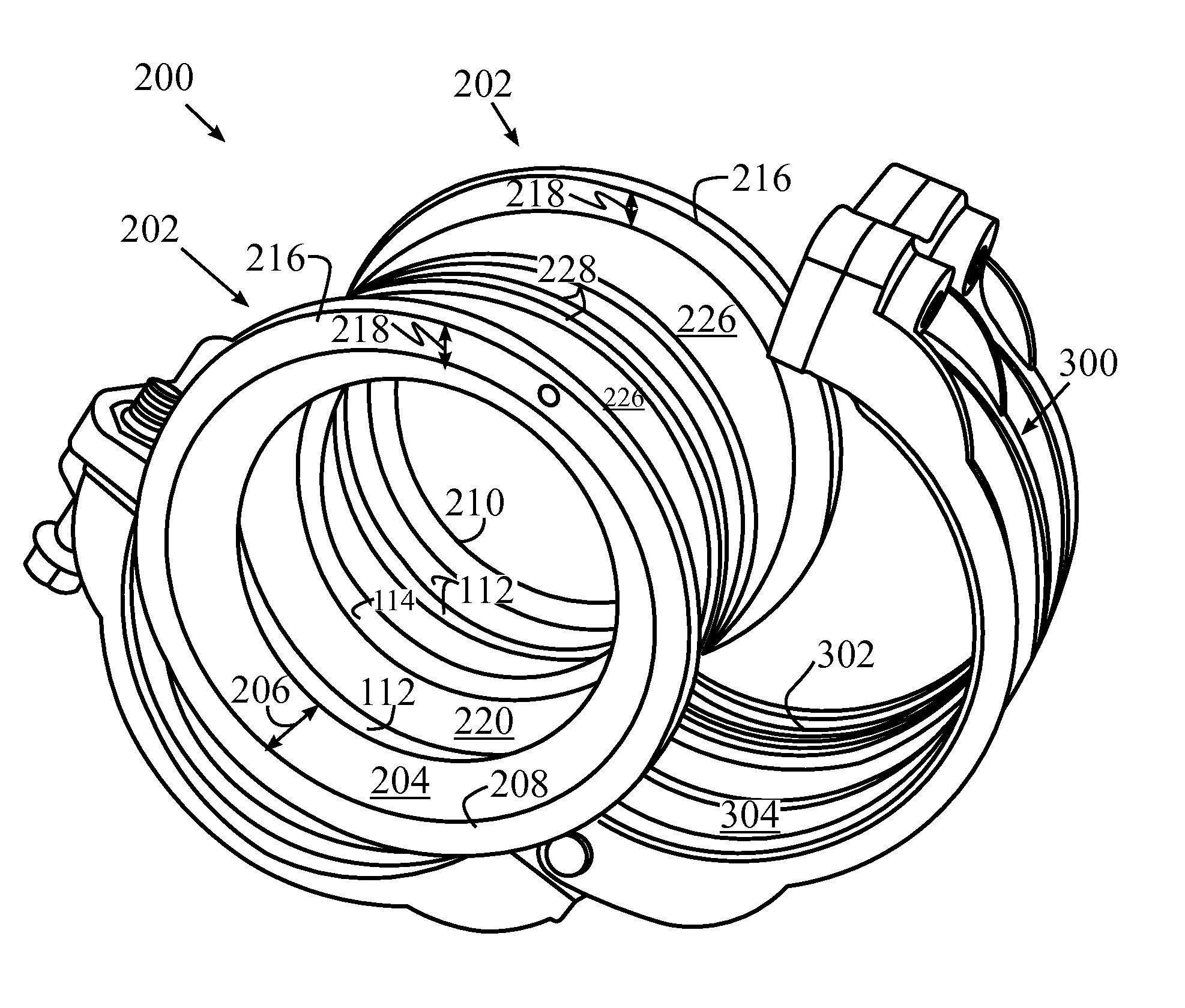
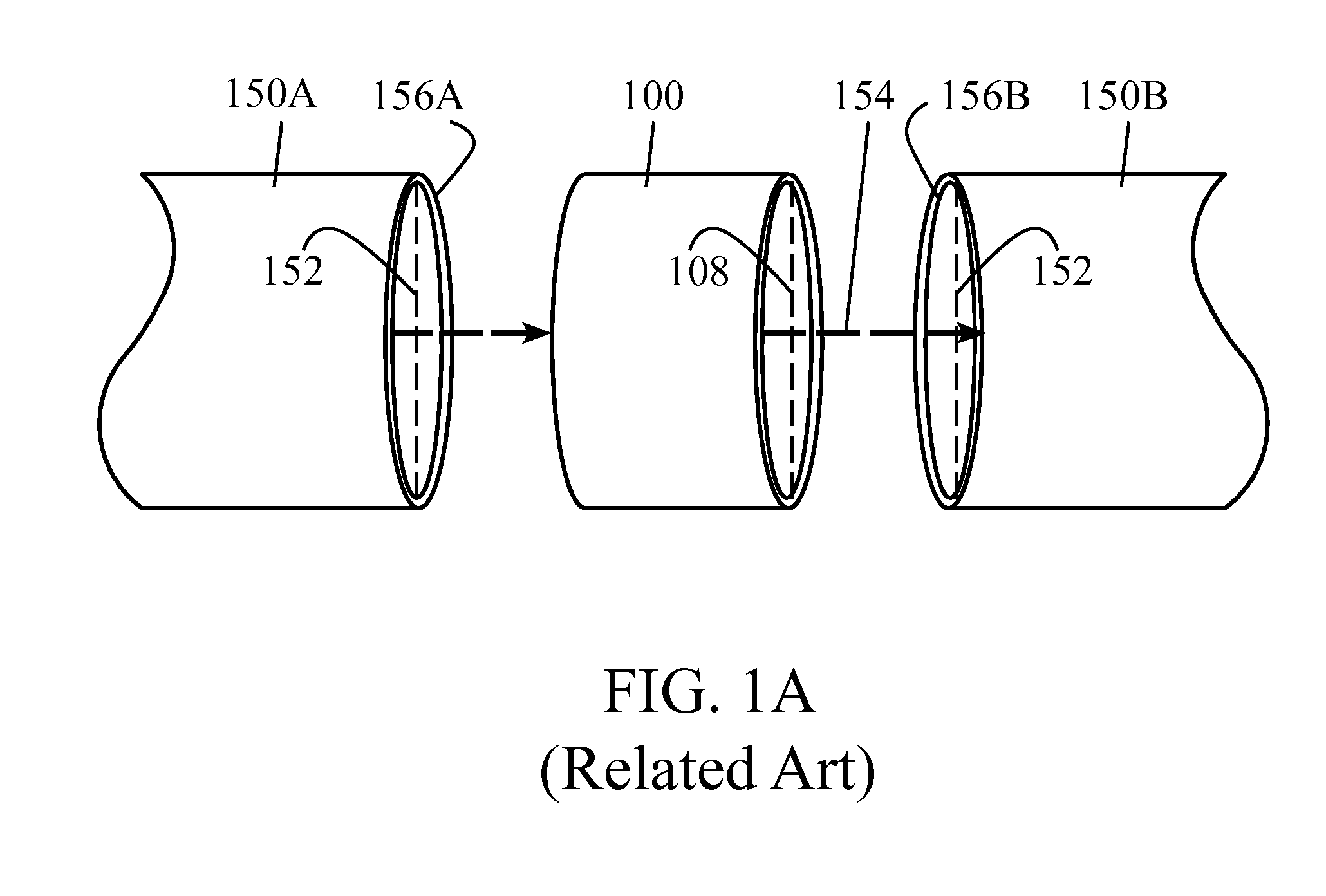
[0083]The present invention provides an improved gasket that is easier to install and capable of speeding up installation of projects where pipes (or pipes and pipe fittings) need to be joined through the use of a coupling device and a gasket therein. FIGS. 2A to 2D are non-limiting exemplary illustrations of the various views of a gasket in accordance with the present invention. As illustrated, the present invention provides a gasket 200 with an axial length 234 (FIG. 2C), comprising a chamfered opening 202 for facilitating insertion of an object (e.g., pipe segments 150A and 150B, illustrated in FIGS. 4B and 4C) within the gasket 200.

[0084]The chamfered opening 202 is comprised of a flexible flap 204 th...


PUM


Abstract

The present invention includes a gasket with a chamfered opening for facilitating insertion of an object within the gasket. The chamfered opening is comprised of a radially symmetric sloping surface that radially extends from a distal edge and uniformly converges inwardly at an angle into a cavity of the gasket toward a central longitudinal axis of the gasket, forming a chamfered edge.

Description

CROSS-REFERENCE TO RELATED APPLICATIONS[0001]This Application claims the benefit of priority of the co-pending U.S. Utility Provisional Patent Application No. 61 / 405,362, filed 21 Oct. 2010, the entire disclosure of which is expressly incorporated by reference herein.BACKGROUND OF THE INVENTION[0002]1. Field of the Invention[0003]This invention relates to gaskets and, more particularly to gaskets for joining segments of pipes, or joining segments of pipes and fittings.[0004]2. Description of Related Art[0005]Conventional couplers such as gaskets are well known and have been in use for a number of years. FIGS. 1A and 1B are exemplary illustrations of a typical conventional gasket 100 that is used to couple or join pipe segments 150A and 150B. As illustrated in FIG. 1A, the gasket 100 is typically molded in a cylindrical shape using a variety of methods, a non-limiting example of which may be injection-molded rubber (or any elastomeric compound, a non-limiting example of which may inc...

Claims


Application Information

Patent Timeline
IPC IPC(8): F16L21/00
CPCF16L21/005F16L21/065
Inventor SARKISIAN, ARMONDSARKISIAN, ALFREDSARKISIAN, SARO
Owner SARKISIAN ARMOND
Why Eureka
Try Eureka