Imaging apparatus

a technology of imaging apparatus and telescopic lens, which is applied in the field of imaging apparatus, can solve the problem that the automatic zoom control function cannot suitably perform the zoom control

Active Publication Date: 2012-04-26
CANON KK
View PDF5 Cites 69 Cited by
  • Summary
  • Abstract
  • Description
  • Claims
  • Application Information

AI Technical Summary

Benefits of technology

[0009]The present invention relates to an imaging apparatus capable of performing suitable automatic zoom control in consideration of face inclination of a subject image.

Problems solved by technology

Therefore, the automatic zoom control function cannot suitably perform zoom control according to a subject-based photographing composition with which a predetermined range of the subject image fits into the angle of view, such as upper body close-up and entire body images.

Method used


Image

  • Imaging apparatus
  • Imaging apparatus
  • Imaging apparatus

Examples


Embodiment Construction

[0027]Various exemplary embodiments, features, and aspects of the invention will be described in detail below with reference to the drawings.

[0028]A digital camera 201 as an imaging apparatus according to a first exemplary embodiment of the present invention will be described below with reference to FIGS. 1 to 11.

[0029]A configuration of the digital camera 201 according to the first exemplary embodiment will be described below with reference to FIGS. 1A, 1B, and 2.

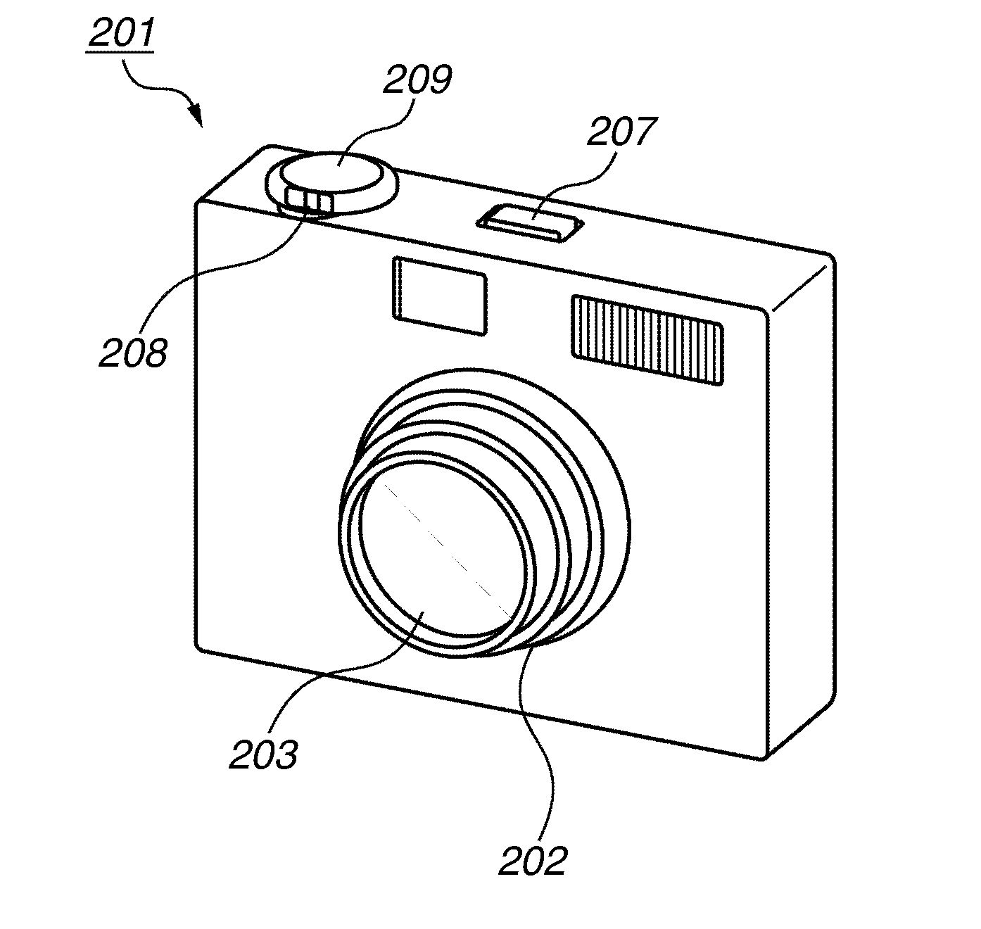
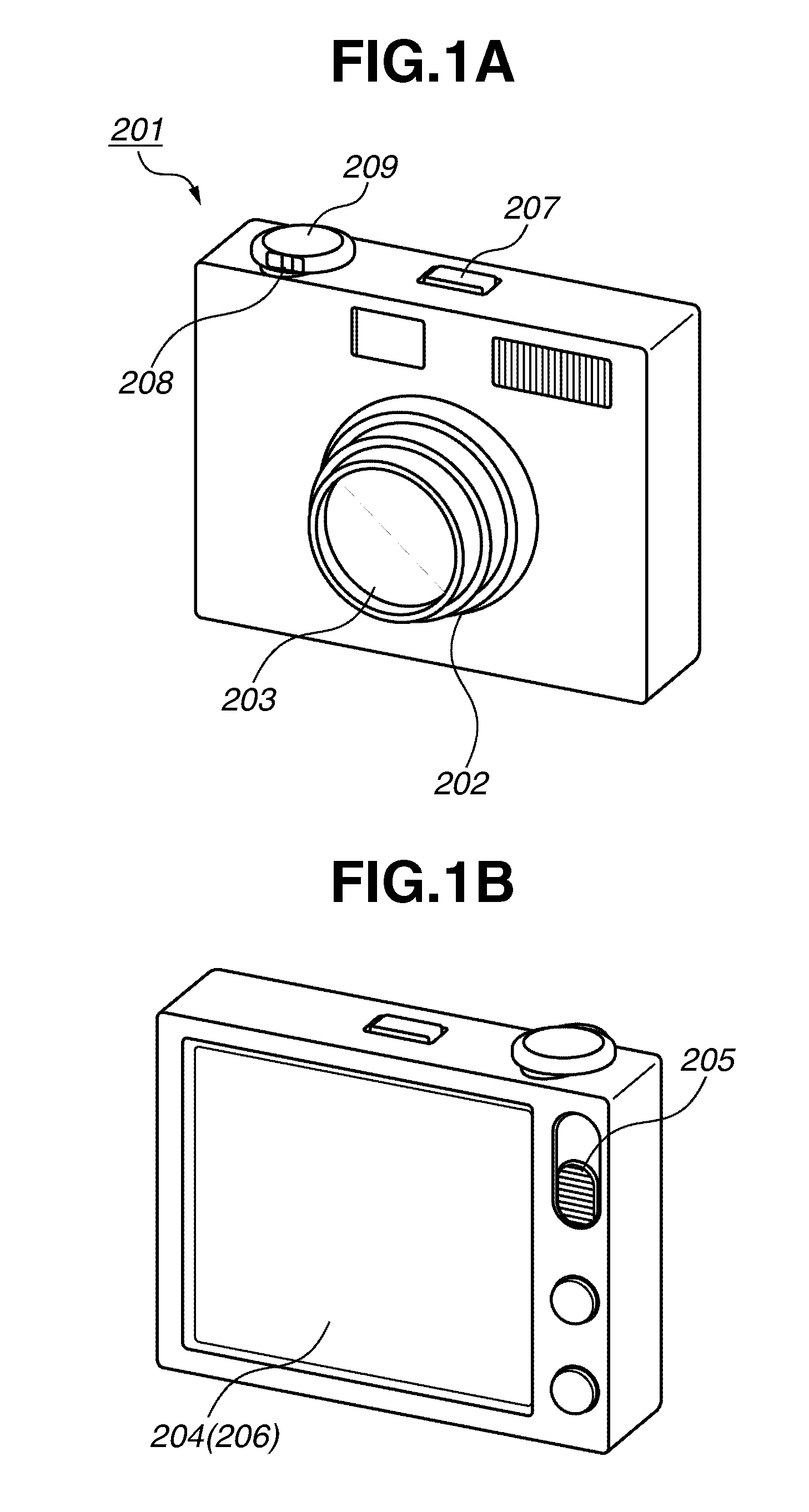
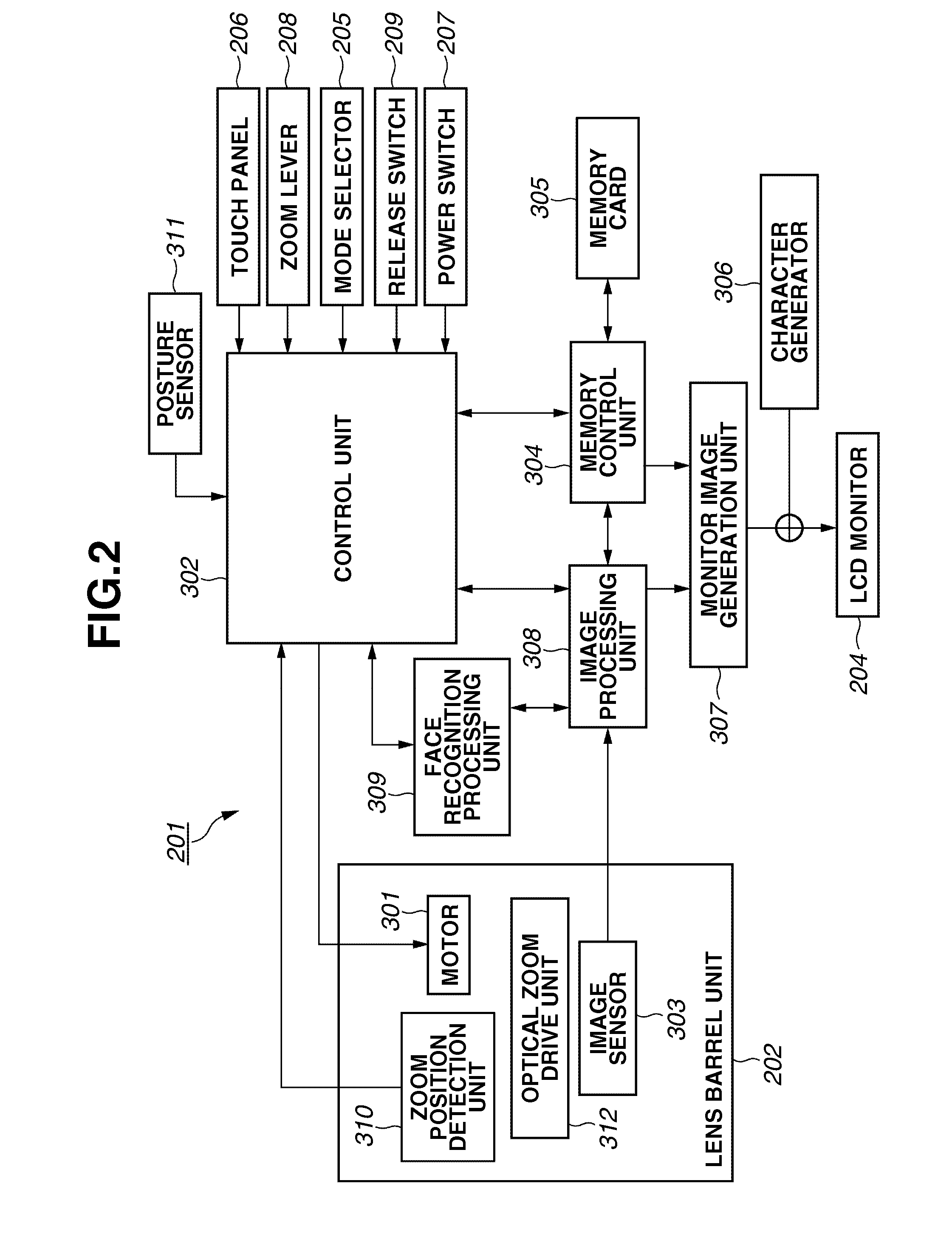
[0030]FIGS. 1A and 1B illustrate an appearance of the digital camera 201. FIG. 1A is a bird's-eye view illustrating the front face of the digital camera 201. FIG. 1B is a bird's-eye view illustrating the rear face of the digital camera 201. FIG. 2 is a block diagram illustrating the configuration of the digital camera 201.

[0031]The digital camera 201 includes a rectangular parallelepiped housing. A lens barrel unit 202 extends from a surface (hereinafter referred to as front face) of the digital camera 201. The lens barrel...


PUM


Abstract

A controller controls a photographing angle of view based on the face size detected by the face size calculation unit and the face inclination detected by the face inclination detection unit, wherein the controller controls the photographing angle of view so that a size with respect to the photographing angle of view of the subject image recognized by the face recognition unit becomes a predetermined size.

Description

BACKGROUND OF THE INVENTION[0001]1. Field of the Invention[0002]The present invention relates to an imaging apparatus capable of performing automatic zoom control.[0003]2. Description of the Related Art[0004]In recent years, a subject recognition technique and a face recognition technique have been mounted on imaging apparatuses such as digital cameras. Such imaging apparatuses perform control such as focusing point movement, release control, and image quality parameter change according to results of subject and face recognitions.[0005]As described below, automatic zoom control based on the subject recognition technique is known.[0006]A conventionally known television camera apparatus reduces camera operator's burden by calculating an on-screen position and a size of a recognized subject image and automatically controlling a camera position and a zoom distance following subject's motion to achieve a preset photographing composition.[0007]Japanese Patent Application Laid-Open No. 200...

Claims


Application Information

Patent Timeline
Patent Type & Authority Applications(United States)
IPC IPC(8): H04N5/228
CPCG06K9/00255H04N5/23219H04N2201/0084H04N5/23296H04N5/23293G06V40/166H04N23/61H04N23/611H04N23/634H04N23/632H04N23/69
Inventor HOSOE, HIROSHI
Owner CANON KK
Why Eureka
Try Eureka