Liquid crystal display

a liquid crystal display and display technology, applied in the field of liquid crystal display, can solve the problems of poor display visibility in a dark room, unnecessarily turning on the backlights of end users, and quick drain of battery in cellular phones and other mobile appliances, so as to reduce sensitivity, prevent malfunction, and simple structure

Active Publication Date: 2007-10-04
JAPAN DISPLAY WEST
View PDF15 Cites 44 Cited by
  • Summary
  • Abstract
  • Description
  • Claims
  • Application Information

AI Technical Summary

Benefits of technology

[0010]An advantage of the invention is to provide an LCD having a simple structure to incorporate an ambient light photosensor detecting external light in a substrate to avoid malfunction and reduced sensitivity due to light from its backlights.
[0011]Another advantage of the invention is to provide an LCD that automatically controls on / off of its backlights not only at a predetermined level of brightness but also at brightness levels desired by end users.
[0012]A liquid crystal display (LCD) according to a first aspect of the present invention includes a liquid crystal panel having an active matrix substrate, a opposed substrate, and a liquid crystal layer interposed between the two substrates; an ambient light photosensor having a semiconductor layer for detecting external light; a photodetector unit having a first capacitor in which a predetermined reference voltage is charged and a voltage charged by leakage current of the ambient light photosensor is lowered; and an ambient light photosensor reader unit for reading a voltage charged in the first capacitor for a predetermined read period. The photodetector unit is disposed on a surface of the active matrix substrate that is in contact with the liquid crystal layer, and the surface of the photodetector unit except for the semiconductor layer and its periphery is covered by a light-shielding layer.
[0013]Since the surface of the photodetector unit provided to the active matrix substrate except for the semiconductor layer that detects external light and its periphery included in the ambient light photosensor is covered by a light-shielding layer, light from the backlight that has passed through the active matrix substrate and been reflected on a opposed substrate or the like can be prevented from entering the ambient light photosensor. It is therefore possible to prevent malfunction or reduced sensitivity of the ambient light photosensor. This feature is achieved with a simple structure in which the photodetector is simply covered.
[0014]In the above-described LCD, preferably, the photodetector unit and the ambient light photosensor reader unit are provided to the surface of the active matrix substrate that is in contact with the liquid crystal layer. In the photodetector unit and the ambient light photosensor reader unit, the surface of the photodetector unit except for the semiconductor layer that detects external light and its periphery is covered by a light-shielding layer.
[0015]Since the ambient light photosensor reader unit as well as the photodetector unit is provided to the active matrix substrate, the ambient light photosensor reader unit is also provided with the light-shielding layer in addition to the above-mentioned advantage. It is therefore possible to easily shield the ambient light photosensor reader unit from light.

Problems solved by technology

Since the reflective LCDs use external light as their light source, they present poor display visibility in a dark room.
Here, the end user may unnecessarily turn on the backlights even when sufficient external light is available.
When this happens, waste power consumption increases to cause quick battery drain in cellular phones and other mobile appliances.
However, the LCD including a TFT ambient light photosensor integrally on its substrate as described in JP-A-2002-131719 may cause malfunction or reduced sensitivity under the influence of light emitted from the backlights. FIG. 12 is a sectional view schematically showing a TFT ambient light photosensor included in a known LCD.
When the light L2 comes in, an extra dark current flows in the TFT ambient light photosensor, thereby causing malfunction or reduced sensitivity of the TFT ambient light photosensor.

Method used


Image

  • Liquid crystal display
  • Liquid crystal display
  • Liquid crystal display

Examples


first embodiment

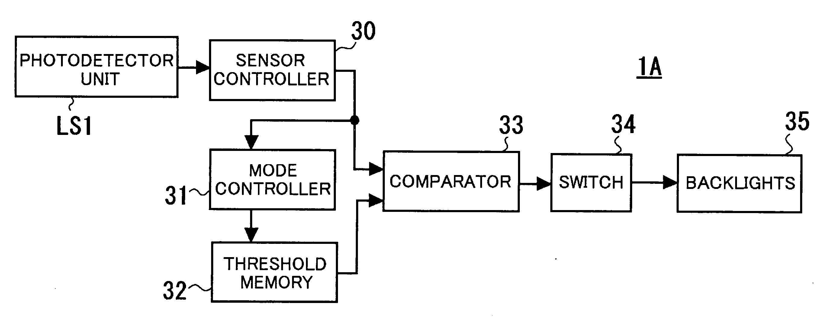
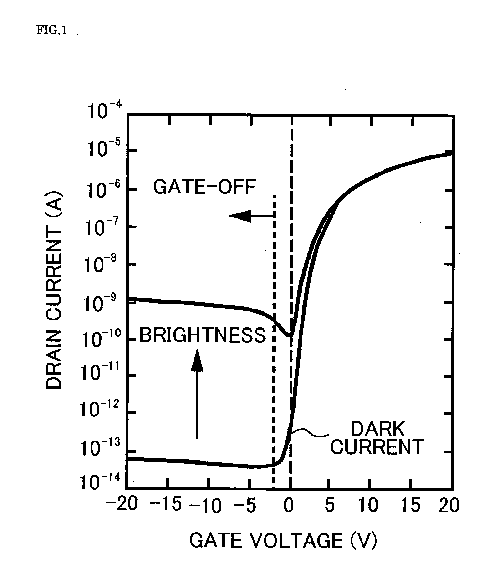
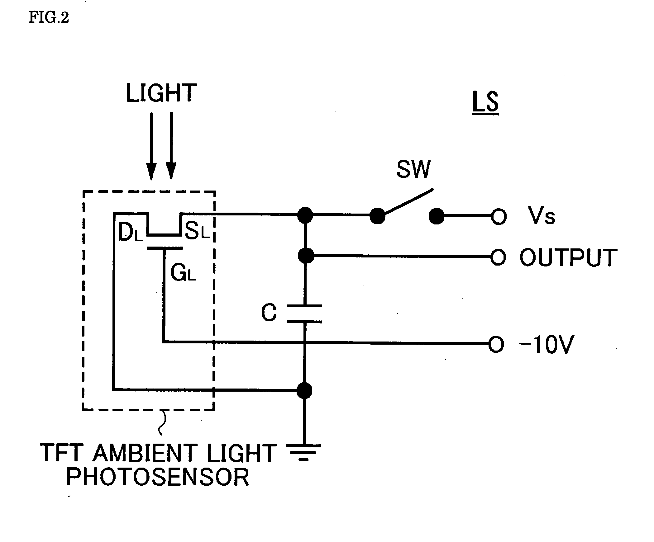
[0038]Referring to FIGS. 1 through 3, the known operation principle of a TFT as an ambient light photosensor (hereinafter referred to as the “TFT ambient light photosensor”) and a driving circuit therefor will be described. FIG. 1 shows an example of the voltage-current curve of the TFT ambient light photosensor. FIG. 2 is a circuit diagram of a photodetector unit using the TFT ambient light photosensor. FIG. 3 shows the voltage-time curve at both ends of a capacitor C included in the circuit diagram of FIG. 2 with different brightness levels. Like reference numerals in FIG. 2 designate like structural elements.

[0039]The TFT ambient light photosensor has practically the same structure as another TFT serving as a switching element for an active-matrix LCD panel. Referring to FIG. 1, an ultra-low dark current flows in the TFT ambient light photosensor in the gate-off state when it is light-shielded, and a leakage current increases depending on the intensity (brightness) of light shed ...


PUM


Abstract

A liquid crystal display (LCD) 1 according to an embodiment of the present invention includes a liquid crystal panel having a TFT substrate 2, a CF substrate 25, and a liquid crystal layer 14 interposed between the two substrates; a TFT ambient light photosensor having a semiconductor layer 19L for detecting external light; a photodetector unit LS1 having a capacitor Cw in which a predetermined reference voltage is charged and a voltage charged by leakage current of the TFT ambient light photosensor is lowered; and an ambient light photosensor reader unit Re1 for reading a voltage charged in the capacitor for a predetermined read period. The photodetector unit is disposed on a first surface of the TFT substrate 2 that is in contact with the liquid crystal layer, and the surface of the photodetector unit except for the semiconductor layer 19L and its periphery is covered by a light-shielding layer 21. It is therefore possible to provide an LCD in which malfunction or reduced sensitivity of its ambient light photosensor due to light from its backlights is prevented with a simple structure.

Description

BACKGROUND[0001]1. Technical Field[0002]The present invention relates to a liquid crystal display, particularly to a liquid crystal display that has a light source, such as a backlight and a front light, whose brightness level can be automatically changed depending on the brightness of external light.[0003]2. Related Art[0004]The use of liquid crystal displays (LCDs) has been widespread not only for information and communications devices but also for general electric appliances. Among them, reflective LCDs that require no back or side lights (hereinafter collectively referred to as “backlights”), unlike transmissive LCDs, have been widely used for mobile applications in order to reduce power consumption. Since the reflective LCDs use external light as their light source, they present poor display visibility in a dark room. To address this problem, there have been developed reflective LCDs employing front lights (e.g., see JP-A-2002-131742) and semi-transmissive LCDs having a combina...

Claims


Application Information

Patent Timeline
Patent Type & Authority Applications(United States)
IPC IPC(8): G09G3/36
CPCG09G3/3406G09G3/3648G09G2360/144G01J1/4204G02F2001/136245G02F1/1336G02F1/136209G02F1/13624G02F2001/133618G02F1/13318G02F1/133618G02F1/136245
Inventor SANO, YUTAKAKUNIMORI, TAKASHITANAKA, TOSHIHIKOYASUMORI, MASANORI
Owner JAPAN DISPLAY WEST
Why Eureka
Try Eureka