Automated superconducting magnet ramp-up system and method

a superconducting magnet and automatic technology, applied in the direction of magnetic measurements, instruments, measurement devices, etc., can solve the problems of reducing affecting the performance of the condensing system components, and relatively high production and maintenance costs of cryogenic liquids, such as liquid helium

Inactive Publication Date: 2005-05-26
GE MEDICAL SYSTEMS INC
View PDF2 Cites 40 Cited by
  • Summary
  • Abstract
  • Description
  • Claims
  • Application Information

AI Technical Summary

Benefits of technology

[0014] The technique may provide for automatically controlling a rate of supply current to the magnet based on several constraining target parameters. The target parameter may include magnet frequency or field strength, as well as magnet current and magnet temperature. Operating values of the constraining parameters may be measured and compared to set points of the constraining parameters to control the rate of supply current. The technique may include measuring magnet temperature, magnet frequency, and magnet field strength, and magnet current.
[0015] The constraining parameters may include magnet current during a first phase of the ramp-up and include magnet frequency or field strength during a second phase of the ramp-up. Additionally, the constraining parameters during the first phase and second phase may include magnet temperature. The magnet temperature may include magnet coil temperature, cryogen temperature, or radiation shield temperature. In one embodiment, the magnet temperature is kept below 7 K, the total increase in magnet temperature over the ramp is controlled at less than +2 K, and the rate of supply current is controlled in the range of 0 to 4 amperes per minute.

Problems solved by technology

Cryogenic liquids, such as liquid helium, however, are relatively expensive to produce and maintain.
Additionally, because of the significant difference between the superconducting temperature and ambient temperature, a considerable driving force exists for heat transfer from the environment into the magnet system.
In particular, the performance of the condensing system components may degrade, thereby reducing the efficacy of the condensing system and overall magnet cooling system (cryogenic cooling system).
Moreover, leaks within the cryogen (helium) vessel and / or condensing system, again for example, may also reduce the efficacy of the cooling system.
If the cryogen condensing system is off-line or not condensing effectively, more of the liquid cryogen may begin to volatilize, leading to an increase of pressure in the cryogen vessel (i.e., cryostat).
This conversion of liquid cryogen, such as liquid helium, to its gaseous state, and / or the subsequent venting of the gas, is generally known in the industry as “boil-off.” Venting of the gas leads to permanent loss of expensive cryogen, requiring periodic refilling of the system.
Deactivation of the magnet system may also cause other problems.
These ramps are often problematic and manually intensive, consuming time and creating risk of damage to the magnet system.
For example, certain parts and / or technicians may not be immediately available, leading to longer than necessary downtimes (i.e., off-line time).
Moreover, periods of reactive maintenance may not coincide with already scheduled routine maintenance procedures, leading to duplicative downtimes for the MRI device.
Similarly, when substantial quantities of cryogen are required, very significant costs may be incurred in refilling the serviced system.
And typically, the time associated with problematic ramping (start-up) of the magnet impacts the cost of servicing the magnet, as well as, adds to MRI downtime, events that are to be avoided.
Similar problems exist even prior to the time such magnets are placed in operation, as well as at initial start-up.
Current procedures for building, testing and shipping superconductive magnets do not, however, adequately accommodate boil-off, servicing needs, and ramping consistency.
If the magnet temperature increases excessively, the ramp rate may not be recoverable, but instead the magnet current discharged, and the ramp started over.
Problematic ramping of superconducting magnets increases MRI downtime and costs.
The desire to avoid damaging the magnet generally results in relatively long ramp times. Moreover, it is not uncommon for the service technician or field engineer to overshoot or undershoot the desired magnet current or field strength.
Furthermore, overshooting of the target and / or an excessive ramp rate (e.g., greater than 4 amperes / minute) can cause equipment damage in the superconducting magnet system.
For example, the magnet leads may overheat and fail, and potentially damage the magnets.
Also, the magnet itself may generate significant heat, resulting in the undesirable boil-off of cryogen.
This localized increase in temperature may propagate throughout the magnet, damaging the magnet.
Thus, for the aforementioned reasons, a field engineer may typically err on the side of undershooting the target magnet current.
Unfortunately, however, a conservative ramp-up results in longer ramp times. In general, problems with the ramp-up of the superconducting magnet system can cause equipment damage, venting of helium, increased downtime (and start-up time), increased maintenance costs, and so forth.
Thus, problematic magnet ramping techniques increase the cost of operating and maintaining an MRI system and decrease the availability of the MRI system.

Method used


Image

  • Automated superconducting magnet ramp-up system and method
  • Automated superconducting magnet ramp-up system and method
  • Automated superconducting magnet ramp-up system and method

Examples


Embodiment Construction

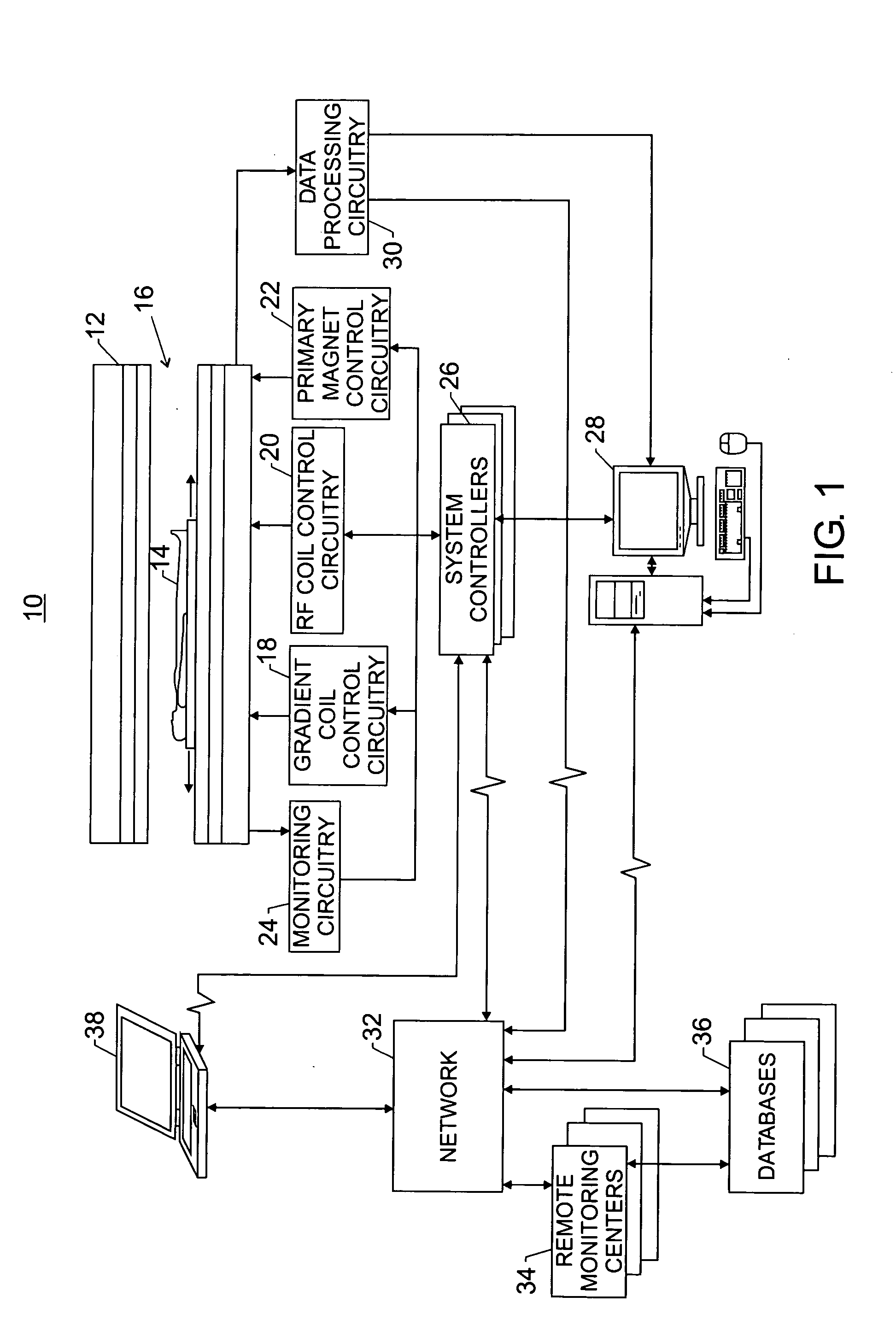
[0022] Turning to the drawings, FIG. 1 illustrates an exemplary imaging network 10. Although described with respect to a medical imaging device, it should be note that the present technique may be applied to any number of systems or devices that employ a cryogen for cooling, such as spectroscopy systems, nuclear accelerators, biological cooling facilities, and power transmission systems, to name but a few. The exemplary imaging network 10 includes a magnetic resonance imaging MRI scanner 12.

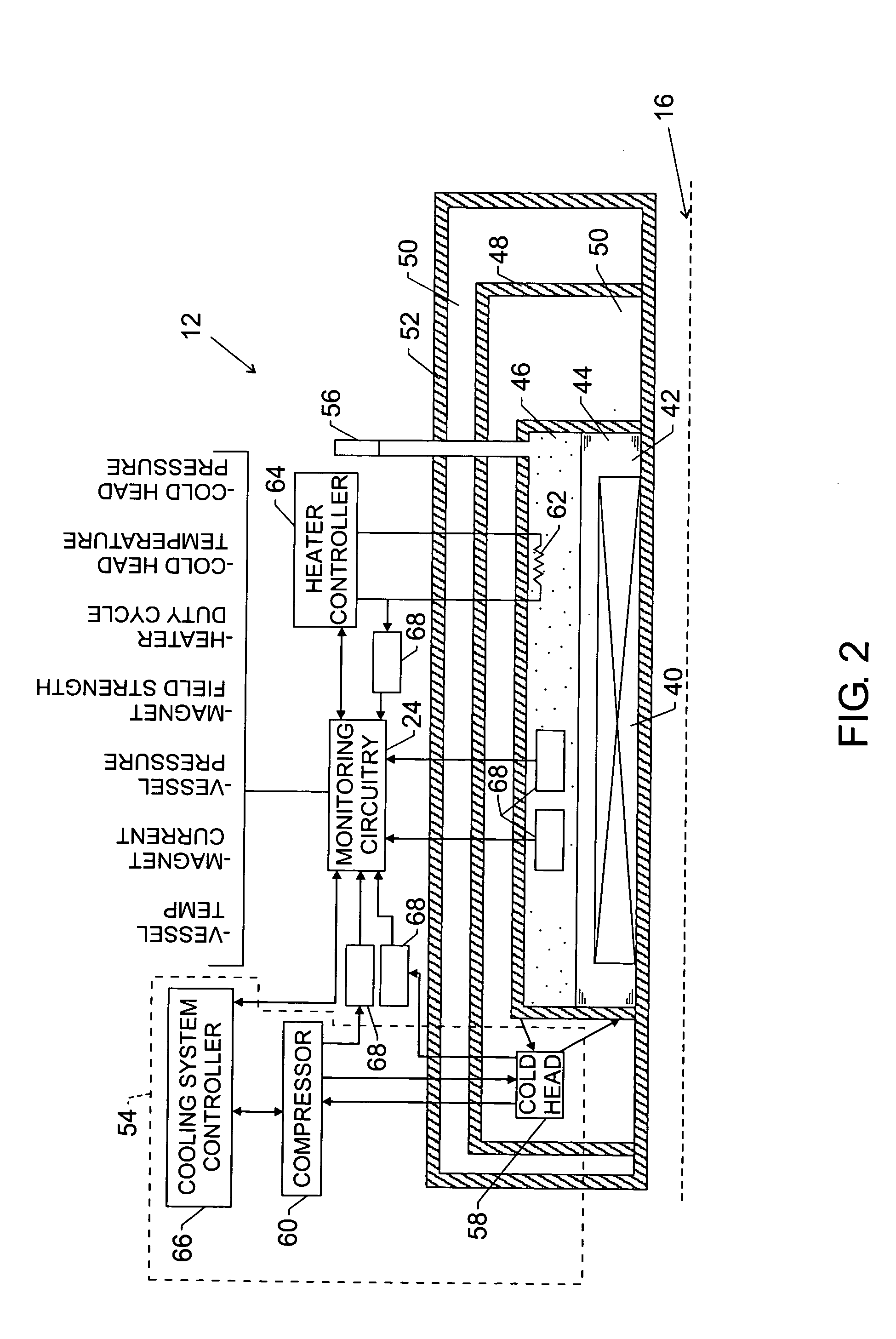
[0023] To obtain diagnostic images of a patient 14, a medical professional may direct the patient 14 into a patient bore 16 of the MRI scanner 12. A main magnetic field (i.e., 0.5-2.0 Tesla) is generally present in the patient bore 16. This field, as discussed further below, is produced by a superconductive electromagnet (see FIG. 2) disposed circumferentially about the patient bore 16. The superconductive electromagnet is maintained at superconducting temperatures (e.g., 1-5 degrees Kelvin) to ...


PUM


Abstract

The present invention provides for a novel technique for placing superconducting magnets into operation. For example, the technique provides for automatically controlling ramp-up of a superconducting magnet. In one aspect, the technique includes connecting a power supply to the magnet, determining constraining parameters of the ramp,-up automatically applying power to the magnet, automatically controlling the ramp-up based on the constraining parameters, and wherein the ramp-up is complete upon reaching a predetermined value of a target parameter.

Description

[0001] The present technique relates to medical imaging devices and other systems employing superconducting magnet systems. More particularly, the invention relates to a technique for bringing a superconducting magnet into operation in an automated fashion following installation or servicing. [0002] A number of important applications exist for superconductive magnet systems. These include imaging systems, as for medical imaging, as well as spectrometry systems, typically used in materials analysis and scientific research applications. The present technique relates to management of cryogenically cooled superconductive magnets, and particularly to the monitoring and servicing of such systems. Although reference is made throughout the following discussion to imaging systems, it should be borne in mind that the technique is applicable to a range of systems that utilize cryogenically cooled superconducting magnets. [0003] Imaging devices are omnipresent in typical medical environments. M...

Claims


Application Information

Patent Timeline
Patent Type & Authority Applications(United States)
IPC IPC(8): G01R33/3815
CPCG01R33/3815
Inventor KNIGHT, LARRY KEITH
Owner GE MEDICAL SYSTEMS INC
Why Eureka
Try Eureka